If you want to have outputs you should use a shorting (switched) jack and run the outputs in series with the jack, where it will output to the RCA if the jack is empty and to the headphone if they are plugged in.
Yes you can parallel outputs if you like.
You can buss the grounds if you like, it will probably work fine, but grounding and ground loops can be tricky, so be willing to experiment if it’s not quiet.
Yes you can parallel outputs if you like.
You can buss the grounds if you like, it will probably work fine, but grounding and ground loops can be tricky, so be willing to experiment if it’s not quiet.
circuit is so simple that it must be either bad solder joint or wrong resistor value or bad resistor
of course , volume pot must be checked with ohmmeter too, and do your signal measurements with volume pot at max
edit: waidaminit .... you fixed it finally with LM 833 , or not?
Mark60615 - I agree with ZM and suspect you have a bad connection/solder joint somewhere.
I’d still like to see well-lit, in-focus photos and see if there’s anything amiss.
Ok, thanks ZM and 6L6! I'll start checking all of the connections and resistors.
On my Alps pot I'm reading a 1K ohm difference between the two channels at around 30-40% volume.
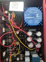
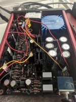
Attached are a few pictures of the build. Summarizing a few of my previous posts, this build is a little weird because I had hard time with the chassis. I used a hacksaw to cut out a corner of the board to get everything to fit. After that I was getting a loud ground hum, so I connected the RCA ground directly to the output ground. That fixed the hum, but I'm not sure why.
Also, here's a link to the full album of photos: whammy photos - Google Photos
Attachments
not a happy camper
Hello,
I bought this kit with the parts included. I had no issues and it played on the first attempt. however, using Sennheiser Momentum 2, I felt my LG G6 with the quad DAC sounds better connected directly to the headphones than via the amp.
I have two issues, and I would appreciate any advice.
Shmulik
Hello,
I bought this kit with the parts included. I had no issues and it played on the first attempt. however, using Sennheiser Momentum 2, I felt my LG G6 with the quad DAC sounds better connected directly to the headphones than via the amp.
I have two issues, and I would appreciate any advice.
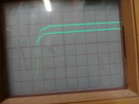
- looking at the scope, entering 8.3KHz square wave, there is a strange rising edge. it worsen as the volume is turned down
- there is a HUGE amount of crosstalk between channels
Shmulik
Attachments
Ground your inputs to the input ground
I do have continuity between the input ground hole next to R39 and the RCA ground tab. I don't have a wire from RCA ground to input ground, but I do have the wire from RCA ground to the GND out hole next to R24.
Do you mean that I should disconnect the wire from GND out and move it back to input ground next to R39? I can try that again, but when I had that configuration before I was getting a really loud hum that only went away when I moved the wire over to the output ground. I'll try it again now.
Ok, I've switched that wire over to input ground now. The hum that I used to get is gone, which is interesting. Maybe before I just had a bad connection on the input ground?
The 15dB imbalance is still there, though. I'll continue testing the resistors and connections.
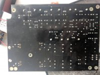
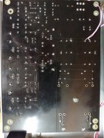
mark60615, the backside PCB pic is a bit out of focus, but from what I can see you need to up the temp on your iron and/or use a wider or cleaner tip and/or more liquid flux. Some of those joints are sketchy. Maybe not the root cause of your present issue, just an observation.
BK
BK
mark60615 as bk856er mentions take a look at R5 and R3 and also on one of the regulators and a bunch of other holes where there looks to be with no solder coming through from the underside.
Reflowing your joints with a hotter iron setting and wider tip is going to help get those nice little fillets will give a better connection
Reflowing your joints with a hotter iron setting and wider tip is going to help get those nice little fillets will give a better connection
I would "re-flow" solder joints. Many looks like they have not got heat enough. A good sign is if the whole solder pad has been "filled" and solder has not "edges" and is shinny.The 15dB imbalance is still there, though. I'll continue testing the resistors and connections.
Also remove R9 R10 R13 R14.
That will make your power supply work properly once the circuit is working properly.
Just checking, did i miss something with regard to R9 R10 R13 R14
why are these no longer needed?
Tony
Neutrik TRS Chassis Jack
GW Wolfman ;
I got mine from Parts Express as they have them a little cheaper than Mouser but the Model number is
Neutrik NJ3FP6C 1/4" Locking Chassis Jack Nickel
Mouser part number
568-NRJ6HM-1-AU

What's the manufacturer and part number of the 1/4" TRS audio jack included in the kit?
GW Wolfman ;
I got mine from Parts Express as they have them a little cheaper than Mouser but the Model number is
Neutrik NJ3FP6C 1/4" Locking Chassis Jack Nickel
Mouser part number
568-NRJ6HM-1-AU
GW Wolfman ;
I got mine from Parts Express as they have them a little cheaper than Mouser but the Model number is
Neutrik NJ3FP6C 1/4" Locking Chassis Jack Nickel
Mouser part number
568-NRJ6HM-1-AU
I love Markertek. Free shipping. Employee owned company.
Neutrik NJ3FP6C 1/4in TRS Panel Mount Locking Jack
back side
here is the back side of the board. I don't see something there that suggests crosstalk, so I'll have to work my way slowly from input to output.
I'll also try the out-in drill of the opamp, though I don't see something wrong there at the moment.
any other ideas are more than welcomed,
Shmulik
here is the back side of the board. I don't see something there that suggests crosstalk, so I'll have to work my way slowly from input to output.
I'll also try the out-in drill of the opamp, though I don't see something wrong there at the moment.
any other ideas are more than welcomed,
Shmulik
Attachments
Just checking, did i miss something with regard to R9 R10 R13 R14
why are these no longer needed?
They've never been needed if the PSU uses the red LEDs and adjust pin bypass capacitors.
here is the back side of the board. I don't see something there that suggests crosstalk, so I'll have to work my way slowly from input to output.
I'll also try the out-in drill of the opamp, though I don't see something wrong there at the moment.
any other ideas are more than welcomed,
Shmulik
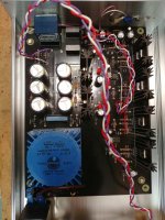
It looks to me like your wires are twisted or braided together and this will give cross talk.
crosstalk
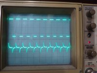
I completely removed the wire from one input connector to the board, and kept the generator connected to the other RCA input connector.
I attached one probe to the live input connector, and the other one to the input resistor of the disconnected channel.
you can see both channels on the scope's screen. the input is ~1.5Vpp, ~8.3KHz. the induced signal is ~30mV peak to peak.
if I connect the wire I removed from one channel to the probe, and just lay it along the still-connected wire, with the square wave on, I see the signal induces to the free wire like to an antenna. I guess something like that happens in parallel traces. I also had to lift the potentiometer by ~1cm, so some parallel wires there also.
besides avoiding parallel input wires, I don't have a good idea how to deal with this.
Attachments
- Home
- Amplifiers
- Pass Labs
- "WHAMMY" Pass DIY headphone amp guide