Something about the badge and the form factor has me wanting to tweak your design into a Bel Canto chassis every time I try to think of a way to do anything other than what's already there. So I guess don't listen to me, I'll just make your chassis a weird clone of someone's design.
Aha... I see what you mean: getting the knobs and jacks inside the "badge". Yeah, that will bring a whole lot of other mechanical problems into the mix: require thicker glass, need to ensure grounding through the glass.
They look nice, but probably not the route I want to take right now.
Any opinions on the electrical difficulties of the last design?")
Thanks,
Rafa.
They look nice, but probably not the route I want to take right now.
Any opinions on the electrical difficulties of the last design?
Thanks,
Rafa.
Looks like the AC wiring should be easy to keep a reasonable distance away from everything except maybe the pot (assuming you go up and over along the top edge in front). Twist the leads and keep them near the right edge of the chassis and away from things and it shouldn’t be an issue. My DAC has the transformer mounted dead center and the wires are running across plenty of stuff without causing problems, so you’re probably putting more effort in to isolating everything than you absolutely need already. Should work out great.
Plenty of amps run off board pots to no ill effect. Unless you use garbage wire or run way too much of it, it should be a negligible difference. My other amp does it and AMB makes a board specifically to do it with an RK27.
Looks like you’ve got a pretty solid plan. Should come out very nicely when it’s all said and done.
Whammy sings for the first time.....
But when connected to F6, normal listening level with pot full clockwise position !
F6 is only 11 o'clock position when driven by BA3FE unit.
How to use Whammy as a Preamp ?
Increase R8 and R4 from 4.75K to 10K will give you anothe 6 dB gain.
PSU built and working!! My + voltage is 16.81v and the negative one is -16.9v. Almost textbook 15v + 1.8 forward LED voltage.
I have to admit I do not understand why without load the rectifiers + LEDs should read 18+ volts as described on the first post by 6L6. But I'm a bit happier with these numbers. Obviously, I hope they don't fall under those values after load.
After power up and testing, the caps had enough juice to keep the LEDs on for about an hour after I turned the power off!
Really happy. It's the first PSU I have ever built.
Best regards,
Rafa.
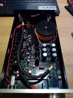
Finaly i got to drill som vents on the top. and checked some temps yesterday. After about 6hours running:
transformer is 30VA 2x18V.(meassured +/-25Vdc ish before regulators). 7815/7915 regulators (naked regulators option).
outputs is IRF 610/9610 running at 60mA bias.
With the lid on, i got 31ish celsius under the lid, and 41ish celsius on the regulator sinks. i did not bother to check the output sinks as they are way cooler then the regulator sinks. It looks like i can up the bias to 120mA as planed. i was worried about the regulator sinks if i did so. thinking i might be better of with a 2x15V transformer.
Attachments
I have a question regarding "chassis ground" (wall third leg) and PCB ground regarding the phono connector. (If this has been asked before, I apologize, I have read all the thread but don't remember reading about this).
The "PCB ground" or "Audio Ground" as it is written in the PCB is completely isolated from the chassis, which is connected to safety ground. There is a cap between the audio inputs and this safety ground which are still 'isolated' due to the cap.
BUT... the audio connector shares the shaft with its ground. Once I connect the "audio ground" to the connector and the connector to the chassis... I'll be linking the safety ground to the audio ground.
Is this good or even expected? Should I prevent this from happening and isolate the frontal noose of the audio jack from the chassis?
Incidentally, same question applies to the additional pair of RCA outputs I'm going to install. Do these need to be isolated from the chassis? Do they need a cap as well?
Thanks for any insight and all the help,
Best regards,
Rafa.
you should have isolators between the RCA Connector and chassis. so only Connection to chassis should be signalground thru a 0.1-0.47uF cap.
Additional RCA shares signal ground and safety earth so no akstra cap is needed. they all are grounded be the same cap.
Additional RCA shares signal ground and safety earth so no akstra cap is needed. they all are grounded be the same cap.
Last edited:
Are you using the kit jack or that Neutrik jack you mentioned? The Neutrik can be run with the flange floating or tied to ground if you’re really concerned about it.
You could always isolate the metal bushing on any normal TRS jack like the RCAs though if you find you need it. You’d have to enlarge the mounting hole to fit a sleeve, but a nylon flanged bushing makes for great electrical isolation.
You could always isolate the metal bushing on any normal TRS jack like the RCAs though if you find you need it. You’d have to enlarge the mounting hole to fit a sleeve, but a nylon flanged bushing makes for great electrical isolation.
I just got my kit today. Looks very nice. There is a big power connector unit with IEC male connector, switch and fuse holder and noise filter. What are the plans for making a dedicated chassis for the Whammy? …….and will there be cut out for this huge power connector unit in such a chassis? …...I am not in a hurry so I can wait long time for such a chassis...…..
- Home
- Amplifiers
- Pass Labs
- "WHAMMY" Pass DIY headphone amp guide