Hello everybody, I'd very much like to build this wonderful amp, but ordering the pcb from the US to Europe is prohibitly expensive ��
I did download gerber files I found on this forum but JLCPCB told me that the drill file does not match the gerber files.
Can someone point me to a gerber file that should work? I'd be eternally grateful ��
Corrected Drill file is in post #457
PassDIY Headphone Amp
Elsewhere on this site, Mark Johnson describes an inline filter for switching supplies, as used here. It's a tiny board with only a few parts. I have quite a few boards here, ready to send out. If you want one or two and are in the US, then they are free. If you want more than two or are not in the US, then I'll ask you to toss me a couple bucks to cover the costs (60 cents per board) and shipping (usually just a first class letter, though more than three boards takes it over an ounce). PM me if you want some.
Note also: Mouser BOM here for one click ordering. This does not include DC jacks, etc, as on the original BOM.
Note also: Mouser BOM here for one click ordering. This does not include DC jacks, etc, as on the original BOM.
Can someone point me to a gerber file that should work? I'd be eternally grateful ��
I accidentally found pcb to order here:
"WHAMMY" Pass DIY headphone amp - Share Project - PCBWay
I accidentally found pcb to order here:
"WHAMMY" Pass DIY headphone amp - Share Project - PCBWay
Yeah, saw that one too, but the Gerber is blocked for downloading, and PCB way is too expensive.
Anyway, my search has ended courtesy of @passive420, as he kindly offered to send a black pcb my way for a modest sum. Thanks again!
you can use these, even if you can hardly squeeze them on original pcb
and they will sound less good than smaller ones
use IRF510/9510
")
I've been looking into finding the optimal fets for this build, and I wonder: Would it not be beneficial to select the lowest rds-ON items?
Like STF45N10F7 for the N channel, and IRF5210PBF for the P channel? These have a much lower on resistance than the suggested parts in the BOM.
The superior thermal efficiency would be very noticable I would say, but maybe I am missing some other parameter.
Hi Swifty,
Newbie here.
I think that Rdson is not the only important parameter, especially when there is 10ohms extra serial resistance on the output.
When I selected parts for my Whammy, I did a quick comparison of the following data available in all datasheets to get an idea on what to get:
My choice was to use IRF9610PBF and IRF610PBF because of their still reasonnably low Q, and symmetric and close N vs P on/off delay/rise/fall times.
Rdson and gFS are in the "not the greatest" range, but I believe those matter less with high impedance headphones and Op Amp closing the loop.
Another thing to consider is to compare certain curves and select parts that have a very close/complementary behavior for the intended bias / operating temperature.
I do not have the eye for that, but maybe some guru can chime in?
Newbie here.
I think that Rdson is not the only important parameter, especially when there is 10ohms extra serial resistance on the output.
When I selected parts for my Whammy, I did a quick comparison of the following data available in all datasheets to get an idea on what to get:
- Rdson
- gFS forward transconductance
- on Delay ; on rise
- off delay ; off fall time
- Qg ; Qgs ; Qgd
My choice was to use IRF9610PBF and IRF610PBF because of their still reasonnably low Q, and symmetric and close N vs P on/off delay/rise/fall times.
Rdson and gFS are in the "not the greatest" range, but I believe those matter less with high impedance headphones and Op Amp closing the loop.
Another thing to consider is to compare certain curves and select parts that have a very close/complementary behavior for the intended bias / operating temperature.
I do not have the eye for that, but maybe some guru can chime in?
A socketed setup would seem easier than soldering with every change; I go back and forth quite a bit, and in addition to being a chore, seems like the trace would eventually lift. A switch would be the easiest long-term but simplest would be finding a gain setting that works for both if I can. Thanks all.
That is exactly what I did; I found some euroblocks that fit the pin spacing and used those. Easy peezy to experiment, as well as lift the board out of the chassis.
--Tom
I accidentally found pcb to order here:
"WHAMMY" Pass DIY headphone amp - Share Project - PCBWay
While the gerbers are posted in the public domain I don’t like the idea of someone putting this up on PCB way and then making a profit off of it.
Not the first time we have seen this.
FYI I don’t get a penny from any of this.
While the gerbers are posted in the public domain I don’t like the idea of someone putting this up on PCB way and then making a profit off of it.
Not the first time we have seen this.
FYI I don’t get a penny from any of this.
As someone who does a lot of open source programming, I can sympathize. I've resigned myself to thinking it's a risk we take to try to make the world a better place. Turns out some people are a**holes, and there's not a lot we can do about it.
It's sick how many people have tried (in some cases successfully) to take advantage of the pandemic to run scams.
That said, I'm sure there are many people who buy PCBs like that who've been duped into thinking that it's OK. I'll be honest: Some years ago, I bought a pair of relay-based volume controls on EBay, of the Aleph P type, thinking that was OK. I'm now pretty sure it wasn't. But they sit today in my balanced B1.
I'll be more careful in future.
Hi Swifty,
Newbie here.
I think that Rdson is not the only important parameter, especially when there is 10ohms extra serial resistance on the output.
When I selected parts for my Whammy, I did a quick comparison of the following data available in all datasheets to get an idea on what to get:
Bigger transistors typically have higher C / Q gate, which means that they will be harder to drive for the Op Amp and have lower bandwidth.
- Rdson
- gFS forward transconductance
- on Delay ; on rise
- off delay ; off fall time
- Qg ; Qgs ; Qgd
My choice was to use IRF9610PBF and IRF610PBF because of their still reasonnably low Q, and symmetric and close N vs P on/off delay/rise/fall times.
Rdson and gFS are in the "not the greatest" range, but I believe those matter less with high impedance headphones and Op Amp closing the loop.
Another thing to consider is to compare certain curves and select parts that have a very close/complementary behavior for the intended bias / operating temperature.
I do not have the eye for that, but maybe some guru can chime in?
What is the value of gate.resistors you settled on? Im going for 250ohm 9610 and 500ohm 610 because i read that their gate capacitance is uneven
I kept stock 499Ohms resistors.
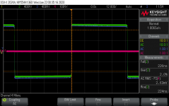
Looking at IRF610 and IRF9610, I found In/Out/Reverse transfert capacitances to be quite close:
What improvement would you expect then?
While measuring 10kHz square via scope, I did not see any asymmetry issue on the rising/falling edges, consistent across levels:
scope_21.png
Looking at IRF610 and IRF9610, I found In/Out/Reverse transfert capacitances to be quite close:
- N - IRF610 140 / 53 / 15 pF
- P - IRF9610 170 / 50 / 15 pF
What improvement would you expect then?
While measuring 10kHz square via scope, I did not see any asymmetry issue on the rising/falling edges, consistent across levels:
scope_21.png
Attachments
A socketed setup would seem easier than soldering with every change; I go back and forth quite a bit, and in addition to being a chore, seems like the trace would eventually lift. A switch would be the easiest long-term but simplest would be finding a gain setting that works for both if I can. Thanks all.
While the gerbers are posted in the public domain I don’t like the idea of someone putting this up on PCB way and then making a profit off of it.
Not the first time we have seen this.
FYI I don’t get a penny from any of this.
I agree. That is totally lame. People need to not bite the hand that feeds them beautifully functional designs like the Whammy.
--Tom
I'm totally stretching the limits of my understanding here but is it even a worthwhile exercise to try and shrink the WHAMMY by making an smd version?
Assuming all else stays the same, 60mA bias through the output stage @ +/-18V =1.08W dissipation. One can find smd mosfets with 2.5W dissipation such as FQT4N25TF and FQT3P20TF and there are surface mount versions of CNY17-3 (in place of the 4N35). Would this be a futile exercise doomed to failure or it is actually one of those 'it should work' things?
The less important question is - is there any point in trying this?
@twitchie
I did something like this a year or so ago to fit on a 120mm by 160mm board to fit in one of the smaller Hammond 1455 series boxes. I did post some pictures to this thread but I'll be darned if I remember the post number. I did modify the design a bit by connecting the output FETs to the unregulated rails to reduce the dissipation in the regulators. The design included a board mounted Schurter IEC and an I2C controlled volume control instead of the analog pot. It all worked out nicely and is one of my go-to headphone amps. If you search this thread you will find a couple of posts about it. I believe 6L6 commented, too.
I did something like this a year or so ago to fit on a 120mm by 160mm board to fit in one of the smaller Hammond 1455 series boxes. I did post some pictures to this thread but I'll be darned if I remember the post number. I did modify the design a bit by connecting the output FETs to the unregulated rails to reduce the dissipation in the regulators. The design included a board mounted Schurter IEC and an I2C controlled volume control instead of the analog pot. It all worked out nicely and is one of my go-to headphone amps. If you search this thread you will find a couple of posts about it. I believe 6L6 commented, too.
@twitchie
I did something like this a year or so ago to fit on a 120mm by 160mm board to fit in one of the smaller Hammond 1455 series boxes. I did post some pictures to this thread but I'll be darned if I remember the post number. I did modify the design a bit by connecting the output FETs to the unregulated rails to reduce the dissipation in the regulators. The design included a board mounted Schurter IEC and an I2C controlled volume control instead of the analog pot. It all worked out nicely and is one of my go-to headphone amps. If you search this thread you will find a couple of posts about it. I believe 6L6 commented, too.
Here it is!

- Home
- Amplifiers
- Pass Labs
- "WHAMMY" Pass DIY headphone amp guide