Hello to everyone!
I 've just ordered the pcb so another whammy is coming soon!
I am reading the thread since the past couple of days and going back and forth to understand better as much as I can. As I have limited experience I would like to ask a few questions before ordering the parts.
1)I was about to go with 18V transformer but I am having second thoughts for a 15V. In case of 18V I've read the recommendation about 15 Ohms R16/R22/R29/R32. In case of 15V what's the recommendation? (assuming in either case LEDs will be used)
2)Following the above question... From my understanding R16/R22 and R29/R32 work as voltage dividers and the Bias can be calculated as 1.2V/R16+R22 .In that case if i want to go with lets say the 18V transformer and aiming for 15 Ohm R16/R22/R29/R32 in practice I am aiming for 30 Ohms R16/R22 and R29/R32 pairs so I could use let's say a 10 Ohm R16 and a 20 Ohm R22. IS THAT CORRECT ?
3)Almost as above.... The gain is calculated by (R8/R12)+1 and (R4/R1)+1 pairs... I believe I can change either R8/R4 or R12/R1 ... correct?
(The above questions about the resistors is because I am about to use dales 0.1% 25ppm that I have some leftovers and I can't find in some values and as my OCD kicks in I want to use the same everywhere..... I know...don't comment....)
4)I want to use a gain selector... the way i am thinking to implement this is by lefting unpopulated R7 and R1 and using a 2x3 rotary switch to hook up the one pad of each resistor to each pole of the switch and adding three different resistors (ex. 1K for 5.75x , 2.21K for 3.15x , 10K for 1.5x) for each toggle... do you find any problems with this implementation?
Lastly can someone tell me the dimensions of the pcb ?
thanks
Thanks a lot.... Somehow i didn't see it.218mm x 160mm (8 5/8" x 6 5/16")
Its on the store page for the pcb.
Alex
This Whammy amp interests me... I think. If only it had switchable gain and a 'turnkey' enclosure or base (meaning no drilling or cutting), I'd be very interested. I have built Dynaco, Hafler and Van Alstine kits, so I feel confident I could complete the board itself without too much difficulty. I use both sensitive IEMs and
I'm sure a gain switch could probably be added by someone who knows what they are doing. But despite the abovementioned projects, I can't really read schematics well and have even less confidence in my ability to do the calculations correctly. Like I said though, I can follow directions of the Heathkit/Dynaco/Hafler variety well enough for it to work when I put the cover on and flip the switch.
A further complication is that my eyes ain't what they usta be. I backed off on installing the 'Booster Board' mod in my O2 and had the now-vanished agdr do it. At least this board seems much more DIY-friendly than the very tightly stuffed O2 board which is cramped because of the (IMO) ill-advised decision to include portability. It really isn't that portable. I have little to no need for a portable amp anyway.
So I guess what I'm looking for is closer to a classic 'kit' than it is to a full-on DIY project. But that option seems to not really exist anymore. I haven't perused the full ~300 pages of this thread though, so does someone who has, know if there are answers to my questions in it? I miss the satisfaction of being able to look at my gear and say to myself, "I made that." It would be nice to have a non-'storebought' amp again for a change.Thoughts/suggestions?
Sounds like a great project. The WHAMMY is wonderful.
With the full kit from the DIY store, a chassis, possibly a breakout board for the pot, a switch, and a few extra resistors, you'd be ready to go.
Chassis choice. You have a few options I can think of. Ready-made with holes on back and front typically drilled for IEC, I/O, and volume pot. You can get them from sellers on many internet sites. It may take some searching. You may need to re-purpose an existing hole or drill a hole for a gain switch.
You could also have ModuShop make you a personalized chassis exactly the way you want it. They can ensure that the holes are where you want them and do beautiful art and lettering for you if you want.
After that, it's a standard build following the exceptional build guide with a tweak for your gain switch. Many people have done switchable gain or altered the fixed gain to suit their needs. Once you're ready, someone will surely chime in with resistor values based on the gain you want and a wiring diagram if needed.
Others will surely have some additional ideas.
Hope it works out well and you enjoy the build and the WHAMMY.
No good...
22 volts AC will give around 31 volts across the cap. Multiply the AC voltage by 1.414 to get the DC voltage (discounting rectifier losses).
Even 35 volts could be marginal when you consider mains voltage tolerance and the fact that transformer ratings are specified at max current. 50 volt working might be a more considered option.
Sounds like a great project. The WHAMMY is wonderful.
With the full kit from the DIY store, a chassis, possibly a breakout board for the pot, a switch, and a few extra resistors, you'd be ready to go.
Chassis choice. You have a few options I can think of. Ready-made with holes on back and front typically drilled for IEC, I/O, and volume pot. You can get them from sellers on many internet sites. It may take some searching. You may need to re-purpose an existing hole or drill a hole for a gain switch.
You could also have ModuShop make you a personalized chassis exactly the way you want it. They can ensure that the holes are where you want them and do beautiful art and lettering for you if you want.
After that, it's a standard build following the exceptional build guide with a tweak for your gain switch. Many people have done switchable gain or altered the fixed gain to suit their needs. Once you're ready, someone will surely chime in with resistor values based on the gain you want and a wiring diagram if needed.
Others will surely have some additional ideas.
Hope it works out well and you enjoy the build and the WHAMMY.
Thanks ItsAllInMyHead. If I can work out the mechanical change I want to make (gain switch, which can be on either front or back panel), the electronic part of the build looks pretty easy... 'Homework' just beginning, including going through the thread to see if anyone else has details on adding a gain switch... Casewise, I could even deal with just a base, á la Bottlehead amps. There are no pets or small humans here to be concerned about.
All the parts I ordered arrived and I just started the putting them tgt. My first time wiring an IEC inlet so I want to make sure I am doing everything correct, so My IEC inlet (Mouser:284-AF-C10-SD) have 3 pins, which I believe top is ground and L and N, it does have a fuse but somehow when i search for wiring methods of IEC with fuse and switch on the internet like (https://www.instructables.com/Wire-Up-a-Fused-AC-Male-Power-Socket/) there are 7 pins on this one so I am a bit confused if anyone can see if I should just ignore and go ahead with the 3 pins.
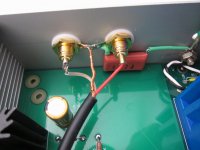
As to the ground wire, I see on the original post on the Guide there's a big red capacitor, if im correct stuck on the wall of the chassis, one leg soldered onto the ground nut screwed on the case which the ground from the IEC inlet also soldered onto, and the other leg of the capacitor is soldered on to the two RCA shoulder washer along with the ground of the input wire.
My question is the big red capacitor necessary? I could be wrong but i dont think i see it on the BOM list, if its not can I have a recommendation of which one to use? Also any RCA jacks you would recommend? preferably on Digikey, seems shipping is the easiest for me in Hong Kong...
Thanks very much
All the parts I ordered arrived and I just started the putting them tgt. My first time wiring an IEC inlet so I want to make sure I am doing everything correct, so My IEC inlet (Mouser:284-AF-C10-SD) have 3 pins, which I believe top is ground and L and N, it does have a fuse but somehow when i search for wiring methods of IEC with fuse and switch on the internet like (https://www.instructables.com/Wire-Up-a-Fused-AC-Male-Power-Socket/) there are 7 pins on this one so I am a bit confused if anyone can see if I should just ignore and go ahead with the 3 pins.
I think your IEC inlet has the fuse and switch wired internally. The other one has bare terminals for the switch and fuse which you are required to wire manually.
Go ahead with the 3 pins, do check and confirm which pins are G, L, N.
I think your IEC inlet has the fuse and switch wired internally. The other one has bare terminals for the switch and fuse which you are required to wire manually.
Go ahead with the 3 pins, do check and confirm which pins are G, L, N.
Thanks for the help! What about the big orange capacitor linking the Ground wire from the input and iec plug, is that needed?
All the parts I ordered arrived and I just started the putting them tgt. My first time wiring an IEC inlet so I want to make sure I am doing everything correct, so My IEC inlet (Mouser:284-AF-C10-SD) have 3 pins, which I believe top is ground and L and N, it does have a fuse but somehow when i search for wiring methods of IEC with fuse and switch on the internet like (https://www.instructables.com/Wire-Up-a-Fused-AC-Male-Power-Socket/) there are 7 pins on this one so I am a bit confused if anyone can see if I should just ignore and go ahead with the 3 pins.
As to the ground wire, I see on the original post on the Guide there's a big red capacitor, if im correct stuck on the wall of the chassis, one leg soldered onto the ground nut screwed on the case which the ground from the IEC inlet also soldered onto, and the other leg of the capacitor is soldered on to the two RCA shoulder washer along with the ground of the input wire.
My question is the big red capacitor necessary? I could be wrong but i dont think i see it on the BOM list, if its not can I have a recommendation of which one to use? Also any RCA jacks you would recommend? preferably on Digikey, seems shipping is the easiest for me in Hong Kong...
Thanks very much
I have attached the picture of the large orange/ref capacitor I was referring to
Attachments
For Mr dbCooper, about setting the gain
I was curious about this and went back to the first post here and under the heading called CIRCUIT, the 3rd line says
Gain is set by R8/R12. Lower gain, make R12 bigger, unity gain, R12=10K
The standard circuit diagram shown has R8 = 4k7r and the R12 = 1kR so this gives gain of 4.7 - do you need any more?
What I would be looking to do is switchable 1x(unity)(low) and 3x (high) settings for my 45Ω Etymotics and 250Ω Beyers respectively. I have a feeling this would require switchable gain to have usable volume control range and quiet operation on each. I'd also prefer not to blow up my Ety's if I can avoid it.
The 'Booster Board'-modded O2 I have now could use a little more than the 0.67 I have now on Low and a little less that the 3.4x I have now on High with the Beyers. That's where I arrive at 1x and 3x. I am moderate (now, anyway) in my listening levels.
The 'Booster Board'-modded O2 I have now could use a little more than the 0.67 I have now on Low and a little less that the 3.4x I have now on High with the Beyers. That's where I arrive at 1x and 3x. I am moderate (now, anyway) in my listening levels.
I have attached the picture of the large orange/ref capacitor I was referring to
I think this cap is there to provide a path to ground for safety in the event of a short or other abnormal event while providing ground loop and noise isolation for the inputs that you might get if you connected input ground to chassis ground.
Someone can correct if my understanding is off target.
I think this cap is there to provide a path to ground for safety in the event of a short or other abnormal event while providing ground loop and noise isolation for the inputs that you might get if you connected input ground to chassis ground.
Someone can correct if my understanding is off target.
Thanks, so by the sound of it it is necessary ..? if so is there one you can recommend on mouser/digikey as i believe its not on the BOM list.
Cheers
As Papa always says: Safety first. So yes, you want that capacitor. It's 0.47uF 250V ceramic or film, Mouser 667-ECQ-E2474JFB e.g.
In the last one I built, I used the 'house ground kit' that's mentioned somewhere else on this site. Let me see if I can find it. It provides a somewhat better connection and is similar to what Pass Labs uses, or so Wayne said.
In the last one I built, I used the 'house ground kit' that's mentioned somewhere else on this site. Let me see if I can find it. It provides a somewhat better connection and is similar to what Pass Labs uses, or so Wayne said.
Last edited:
- Home
- Amplifiers
- Pass Labs
- "WHAMMY" Pass DIY headphone amp guide