For the 0.1uF, i used this one:
https://www.mouser.be/ProductDetail...=sGAEpiMZZMv1cc3ydrPrF7l45uRd9dVhAJeTpZZsyAc=
For the 1k resistor, those ones should work well:
https://www.mouser.be/ProductDetail/Vishay-Dale/RN60D1001FB14/?qs=vEZPefDgUPkcBU7jWJvieQ==
Or
https://www.mouser.be/ProductDetail/Vishay-Dale/RN60C1001DRE6/?qs=2uw1TgnqFv4VHf2oHt50Pg==
For the transformer at the time I only found on digikey i used:
TE2261-ND
Thanks very much @Martigane,
I noticed theres no IEC connector/fuse in the BOM, would something like this work if Im ordering also the Hammond chassis 1455T2201 from Mouser?
https://www.mouser.hk/ProductDetail/Schurter/3-102-855/?qs=w/v1CP2dgqqRUqpibChSVQ==
I also dont have any of the wires used in this project, I have some left over wiring from the Bottlehead Crack I built last year, would that be sufficient? or are there any good quality wires you would recommend for this project please?
Thanks
The IEC should be fine. It's very similar to the one sold in the kit. The kit has this specific part number. The one you've chosen has two pole fuse mounts and a ground choke.
https://www.mouser.com/ProductDetai...O0RPYTQ6z7F1TsVTk7OOoqXXIE9GKPGVs9DxoSRixhYss
Just make sure you get a fuse drawer or confirm with Mouser that you get one included. Within the product description listed within Mouser for your link and mine, it notes that the fuse drawer is sold separately.
Also, that Hammond case is really nice in both appearance and the fact that the boards just slide in. However, just be prepared for a little bit of metal working and a relatively tight fit. There's really not much room on the back panel to fit everything, and there's only one area to fit the IEC due to the clearances. I noticed you linked to Mouser HK. If you do happen to be in HKG, you may consider going to any local electronics market and grabbing a chassis. I don't want to deter you from them, I've bought 4 of them, they are beautiful, IMO, but they're snug. Also, if you do decide that you want to roll op-amps, some of the larger/popular modules (like those from Burson) may not fit due to chassis height and the socket you use, but in mine they're fine. Again, just considerations.
Wiring - I've built a few Cracks. That'll be just fine.
Have fun!")
https://www.mouser.com/ProductDetai...O0RPYTQ6z7F1TsVTk7OOoqXXIE9GKPGVs9DxoSRixhYss
Just make sure you get a fuse drawer or confirm with Mouser that you get one included. Within the product description listed within Mouser for your link and mine, it notes that the fuse drawer is sold separately.
Also, that Hammond case is really nice in both appearance and the fact that the boards just slide in. However, just be prepared for a little bit of metal working and a relatively tight fit. There's really not much room on the back panel to fit everything, and there's only one area to fit the IEC due to the clearances. I noticed you linked to Mouser HK. If you do happen to be in HKG, you may consider going to any local electronics market and grabbing a chassis. I don't want to deter you from them, I've bought 4 of them, they are beautiful, IMO, but they're snug. Also, if you do decide that you want to roll op-amps, some of the larger/popular modules (like those from Burson) may not fit due to chassis height and the socket you use, but in mine they're fine. Again, just considerations.
Wiring - I've built a few Cracks. That'll be just fine.
Have fun!
Last edited:
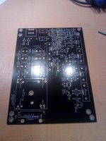
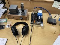
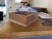
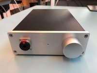
I’ve had my Whammy running and assembled to a prototype chassis for a few weeks now, things are sounding pretty good.
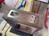
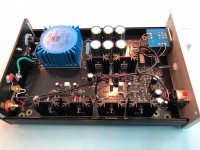
I have attached some pictures of my current setup and also some in progress shots of my chassis.
I have a few questions…
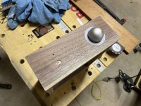
As you can see in the pictures, my chassis has a provision for a power indicator LED on the front, where is the best location to take power for this? I seem to remember some previous posts discussing this but I can’t seem to find them again. From memory, the most convenient locations result in a slow fading light when powering off?
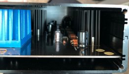
I’m running the Talema 22V (1295-1079-ND) transformer and both regulators are getting pretty hot, the heatsinks are definitely too hot to touch. Is there anything I can do about this? My worry is that I will have heat issues when it is in a fully enclosed chassis.
I’ve seen a lot of comments on how quiet this amp is, mine is not “loud” by any stretch but it isn’t silent, there is definitely a mild hiss when I turn it up past 10 or 11 on the volume dial. Are there any suggestions on how to improve this? I don't currently have space for it but would using a filtered AC inlet help?
I have attached some pictures of my current setup and also some in progress shots of my chassis.
I have a few questions…
As you can see in the pictures, my chassis has a provision for a power indicator LED on the front, where is the best location to take power for this? I seem to remember some previous posts discussing this but I can’t seem to find them again. From memory, the most convenient locations result in a slow fading light when powering off?
I’m running the Talema 22V (1295-1079-ND) transformer and both regulators are getting pretty hot, the heatsinks are definitely too hot to touch. Is there anything I can do about this? My worry is that I will have heat issues when it is in a fully enclosed chassis.
I’ve seen a lot of comments on how quiet this amp is, mine is not “loud” by any stretch but it isn’t silent, there is definitely a mild hiss when I turn it up past 10 or 11 on the volume dial. Are there any suggestions on how to improve this? I don't currently have space for it but would using a filtered AC inlet help?
Attachments
44V CT is a lot of over voltage for the regulators to dissipate. In fact, the raw rectified voltage of around +/- 32V is getting dangerously close to the regulator's max input of 35V. Wayne's original PS design is for a 30V CT transformer.
What is the value of your input pot? 10 or 11 o'clock could be a lot of signal if it is 100K, thus more hiss. That hiss could be in your source, not the Whammy. I see a Burson Classic in the front end. I have the same setup and hear no hiss at any setting below the threshold of pain, even using my Sennheiser HD650s, which look like maybe you have or some other similar 300 ohm Sennheisers.
I don't think a filtered AC inlet would help in the hiss category but can't say since I am using one and have not listened without filtering.
How I did my power LED is in post #1525, located here:
"WHAMMY" Pass DIY headphone amp guide
As you can see in the pictures, my chassis has a provision for a power indicator LED on the front, where is the best location to take power for this? I seem to remember some previous posts discussing this but I can’t seem to find them again. From memory, the most convenient locations result in a slow fading light when powering off?
Assuming you did the LED build, then the 'in' pad of R9 has 18V, so that's an easy place. Use a 10K or so resistor so the light isn't too bright. The other side of R9 is at ground.
This is pretty common and has happen to me when I built my first Whammy; the pot's outer shell still isn't grounded properly and/or you could also have the RCAs at a different ground potential too. Check that the negative side is connected to the same return point that the pot is. The fact that you said it goes away by taking a test lead/clip and connecting it to your board's return point, as well as that you hear the noise go away when you touch the pot itself (thereby grounding it) proves that the shell isn't returning right. In my case, while I had the pot mounted into the face plate with solid contact, the face plate wasn't actually contacting the sides because the anodizing on all sides of the case panels prevented that. This is why one of my first steps when building anything now is to sand off the anodizing on the mating surfaces of the chassis and then use my DVM to prove I have solid continuity.
With that said, IMHO the most straight-forward solution to your problem is to put your project into a chassis.
Thanks for your quick response.
Sorry my electronics knowledge is limited. Are you saying that the 22V secondaries on the transformer I am using are too high for the regulators? This was the transformer recommended in 6L6's original post
"25VA 22V+22V is best and used in this guide."
I should have added that the hiss is only audible with nothing playing through the system, you can't notice it with music on, which is why I am not that worried about it.
What is the value of your input pot? 10 or 11 o'clock could be a lot of signal if it is 100K, thus more hiss. That hiss could be in your source, not the Whammy. I see a Burson Classic in the front end. I have the same setup and hear no hiss at any setting below the threshold of pain, even using my Sennheiser HD650s, which look like maybe you have or some other similar 300 ohm Sennheisers.
Yes I am using the standard 100k Alps
100K input pot is at the high end of values and would potentially reveal more noise (hiss?).
I'm not recommending a change to the transformer. Not too high but higher than it needs to be. Maybe someone else can weigh in on the effect of running higher input voltage to the regulators and if is causes excess heat.
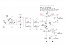
Not sure why 6L6 recommends 22V + 22V. I used 18V + 18V and it works beautifully. You did not say what your regulator scheme is. LED referencing for the 15v chip regulators yields about 15.5V at the opamp rails, well below the 16.5V max specified for the Burson opamp. A 330 ohm R9 and R13 value as shown in the schematic will yield over 19V at the opamp rails if the regulator LEDs are missing or installed backwards. That would definitely cause the Burson to be overloaded.
I'm not recommending a change to the transformer. Not too high but higher than it needs to be. Maybe someone else can weigh in on the effect of running higher input voltage to the regulators and if is causes excess heat.
Not sure why 6L6 recommends 22V + 22V. I used 18V + 18V and it works beautifully. You did not say what your regulator scheme is. LED referencing for the 15v chip regulators yields about 15.5V at the opamp rails, well below the 16.5V max specified for the Burson opamp. A 330 ohm R9 and R13 value as shown in the schematic will yield over 19V at the opamp rails if the regulator LEDs are missing or installed backwards. That would definitely cause the Burson to be overloaded.
Last edited:
22+22V Is what Wayne originally spec'd when the 'standard' voltage was 24V rails feeding an OPA2604 that could drive an F4 to clipping.
That spec was just brought forward through due to momentum. Now that the 2604 is EOL, and most people are not using an F4 to drive a follower power amp to hearing-damage levels, 18+18 is absolutely more than sufficient to give proper excess voltage across the CRCRC filter and the dropout through the regulators.
People wanting to use a great variety of opamps should just choose the 'naked regulator' PSU configuration with 7815/7915 regulators to give 15V rails.
If you want to get all fancy and still have the LED reference with the bypass cap, you could use (2) red LED in series in stead of one with 7812/7912 regulators, which should yield about 15.4V rails.
With regard to temperatures 75 degrees C is toasty warm but the semis will probably be fine for a long time. As an experiment I have run some 7815 NJR regulators at 95 C for a year with no apparent issues. Not a good thing for production but these modern semiconductors are pretty tough.
22+22V Is what Wayne originally spec'd when the 'standard' voltage was 24V rails feeding an OPA2604 that could drive an F4 to clipping.
That spec was just brought forward through due to momentum. Now that the 2604 is EOL, and most people are not using an F4 to drive a follower power amp to hearing-damage levels, 18+18 is absolutely more than sufficient to give proper excess voltage across the CRCRC filter and the dropout through the regulators.
People wanting to use a great variety of opamps should just choose the 'naked regulator' PSU configuration with 7815/7915 regulators to give 15V rails.
If you want to get all fancy and still have the LED reference with the bypass cap, you could use (2) red LED in series in stead of one with 7812/7912 regulators, which should yield about 15.4V rails.
What points do I need to probe to see what voltage I am getting with my current configuration?
Changing to the naked regulator config wouldn't solve my problem would it? As I am dealing with a high input voltage to the regulators?
Is my best option to source an 18V PTX?
With the current PTX, do I need to worry about overloading the PSU filter caps? I am running the Nichicons which are rated to 35V.
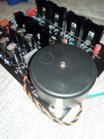
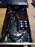
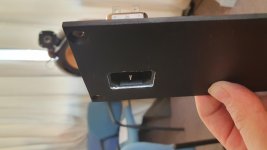
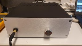
I have used the chassis "Hifi 2000 Galaxy GX283 Chassis - 3mm front plate ; 80x230x230mm"
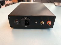
I gives plenty of clearance for IEC connector with filter, allowed for slightly bigger heatsinks.
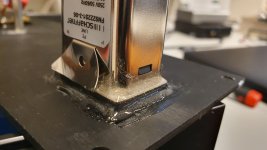
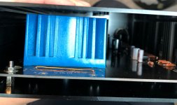
I needed to do some manual work to have a snug fit of the power inlet (if done today I'd choose a different power inlet), see pictures, otherwise it went all smooth.
In addition, I would beef up the heatsink if possible. I glued some extra with epoxy and it works well, with surprisingly good thermal conductivity.
Last thing to consider, you may want to increase the output resistor (decrease output Bias) so that everything will run cooler. (Be aware that this may change the performance)
I gives plenty of clearance for IEC connector with filter, allowed for slightly bigger heatsinks.
I needed to do some manual work to have a snug fit of the power inlet (if done today I'd choose a different power inlet), see pictures, otherwise it went all smooth.
-> One thing you could try is adding extra serial resistors in the CRCRC circuit, maybe double the values. This will have the benefit to decrease the voltage reaching the regulators, as well as increasing the efficiency of the CRCRC filtering.I’m running the Talema 22V (1295-1079-ND) transformer and both regulators are getting pretty hot, the heatsinks are definitely too hot to touch. Is there anything I can do about this? My worry is that I will have heat issues when it is in a fully enclosed chassis.
In addition, I would beef up the heatsink if possible. I glued some extra with epoxy and it works well, with surprisingly good thermal conductivity.
Last thing to consider, you may want to increase the output resistor (decrease output Bias) so that everything will run cooler. (Be aware that this may change the performance)
-> Interesting. I'm also using the 100k alps pot, without any noise even at full volume (Thanks for the tip, I'll try a 47k pot next if I want to try discrete resistor ladder). JermNZ make sure to ground the metal body of the pot and the front panel, it improved the noise on my end when I did not have RC ground loop circuit yet.100K input pot is at the high end of values and would potentially reveal more noise (hiss?).
Attachments
Last edited:
I would be interested to get a list of all the cases you guys have used that are compatible size wise for the PCB.
Please provide any links.
I have used a 1706 chassis from Aliexpress. I have slid the PCB in the side of the chassis on one side and used standoffs in the other.
1706 all aluminum amplifier chassis preamplifier case DAC AMP Enclosure case DIY box (172*60*251mm)|Amplifier| - AliExpress
Attachments
Last edited:
22+22V Is what Wayne originally spec'd when the 'standard' voltage was 24V rails feeding an OPA2604 that could drive an F4 to clipping.
That spec was just brought forward through due to momentum. Now that the 2604 is EOL, and most people are not using an F4 to drive a follower power amp to hearing-damage levels, 18+18 is absolutely more than sufficient to give proper excess voltage across the CRCRC filter and the dropout through the regulators.
People wanting to use a great variety of opamps should just choose the 'naked regulator' PSU configuration with 7815/7915 regulators to give 15V rails.
If you want to get all fancy and still have the LED reference with the bypass cap, you could use (2) red LED in series in stead of one with 7812/7912 regulators, which should yield about 15.4V rails.
I took some measurements (see attached).
It looks like my input voltages to the regulators are at around +- 31.5V which is getting close to the max voltage of the regulators (35V) this must be why they are getting so hot, the output voltage is also bit high (+-17V) especially if I am running Burson opamps.
Will changing to the "naked regulator" configuration to lower my output voltage? If so, it would get me the right output voltage but I'd still have the issue of the regulators running hot.
Or I could try what Martigane suggests below?
-> One thing you could try is adding extra serial resistors in the CRCRC circuit, maybe double the values. This will have the benefit to decrease the voltage reaching the regulators, as well as increasing the efficiency of the CRCRC filtering.
Attachments
Last edited:
you really need xformer with lower voltage
problem with smaller xformers is that they're having so called "poor regulation factor" meaning that voltage difference between full load and light load is huge
they're usually made in a way to have rated voltage at full load
either that , or insert at least 51R/3W in each secondary leg going to diode bridge
Last edited:
I have used a 1706 chassis from Aliexpress. I have slid the PCB in the side of the chassis on one side and used standoffs in the other.
1706 all aluminum amplifier chassis preamplifier case DAC AMP Enclosure case DIY box (172*60*251mm)|Amplifier| - AliExpress
Yeah that looks good
I probably need something one size up, as I am using a transformer mounted external to the board.
- Home
- Amplifiers
- Pass Labs
- "WHAMMY" Pass DIY headphone amp guide