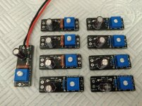
I just thought I would share the LED rectifier of a completed board for those who are interested.")
I need like 4 of those really bad. Any time frame for orders.
Has anybody calculated how long it will take for the supply filter capacitor to discharge, in the LED rectifier circuit of post #2264 ? That's how much time the LED spends, gradually dimming from on to off. Make sure you choose a trimmer setting which puts a reasonable amount of current through the LED. 4mA? 8mA? 2mA? You decide. Then use that trimmer setting in your discharge time calculations.
Has anybody calculated how long it will take for the supply filter capacitor to discharge, in the LED rectifier circuit of post #2264 ? That's how much time the LED spends, gradually dimming from on to off. Make sure you choose a trimmer setting which puts a reasonable amount of current through the LED. 4mA? 8mA? 2mA? You decide. Then use that trimmer setting in your discharge time calculations.
I have tested it with various input voltages and it has a brief fade in and fade out effect. As long as you don't go above 30v input voltage there are no issues. It does the job it's meant to do. End of story.
If you're happy with a brief fade in and fade out effect, then: you're happy. Congratulations!
Others may want instantaneous off and on, such as post #2262 for example. Those builders may wish to slightly modify the circuit, or choose different component values, to get whatever amount of fade-out dimming they prefer.
Others may want instantaneous off and on, such as post #2262 for example. Those builders may wish to slightly modify the circuit, or choose different component values, to get whatever amount of fade-out dimming they prefer.
Sure can they tend to have lower distortion Anyhow. Maybe not the best for bypass but I have done it.
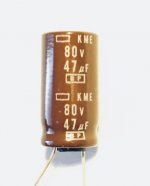
As a bipolar capacitor I unfortunately only have the KME 47uF / 80v BP.
I will first use FC 25uF.
What would be the first choice for C12 / C17 / C22 / C25?
The Nichicon UES or others?
Attachments
Of course I meant 22uF FC's, not 25uF.First choice would be a capacitor of proper value, that fits the PCB.
Anything past that is subjective and open to personal taste and biases. Use what you want and what you think is 'better'.
I will order and try 22uF UES and a few other interesting bipolar capacitors for my next order.
Yes, such an additional film can help the electrolytic capacitors.Hi Roland,
I used Nichicon UES on my WHAMMY, they worked fine.
I did some subjective evaluations against a fixed reference amplifier and found that bypassing those by 1-2uF Wima MKP10 (under elevated PCB) worked really well.
I have a few interesting MKP and KP that I will try out here. I planned the case higher to have some space under the board.
Thanks for the quick feedback. Yes, overall the DC offset looked very very nice, the difference between the channels was interesting. And yes, I can confirm at least, that the mentioned values where those which I've seen on the meter.
Please find attached some pictures. Many thanks again for your help!
Besides the Auricaps, I wanted to ask you if you could detail any other differences between the stock and what you used? It looks for example, that you used some different caps (C12/22?). Did you use the stock/kit TI opamp? Also what is that little "stand off" you used for the LED? I've never seen that before but it looks neat and tidy. It would be great to home in one these low offset figures and how they were achieved.
I just thought I would share the LED rectifier of a completed board for those who are interested.
Love these.. Need them.. Let me know how to send you money for few of these and some power supply boards.
While reading the thread, I came across different recommendations regarding the value for the potentiometer.
Is there a "best" value or recommendation for the pot?
I'm not quite sure why the "standard" for headphone amplifier input potentiometers is 10K. Perhaps to help load the source to reduce hi frequency response, which helps reduce high frequency noise, this being more obvious when listening on headphones.
Rest assured that the Whammy is so quiet and clean that it does not need 10K to tame the source. Mr. Colburn recommends 25K - 100K on his schematic. I find I prefer a 50K pot in my Whammy. This can be somewhat source dependent. The output resistance of a source device can vary from in the tens of ohms to as high as 1 or 2 thousand ohms, with 100 - 200 ohms typical. The higher the output impedance of the source, the more it will lose output as its voltage gets divided by the input pot resistance.
I have listened to different DIY headphone amps, buffers and preamps, comparing 20K, 50K and 100K versions of the Alps RK27 in each and for pretty much most of the circuits, I keep settling on 50K as providing me with the most enjoyable listening experience.
I'm not quite sure why the "standard" for headphone amplifier input potentiometers is 10K. Perhaps to help load the source to reduce hi frequency response, which helps reduce high frequency noise, this being more obvious when listening on headphones.
Noise reduction. The lower value pots will essentially shunt most of the noise picked up on the line level input before amplification. Noise isn't current backed, but the audio is, so lower resistance pots favors the original audio over the low current noise. Hopefully that makes sense.
Hi,
I get burned led once ....check led ..
Do a check of the LED using the diode test on your meter. This will tell you straight away if the LED works, as well as what the polarity is. In generally, the longer leed is positive, but I never assume so after I had one that was clipped and I put it in backwards. Depending on the voltage, this is also how you can fry them.
The other is if the resistor that limits the current into them is non-existent or insufficient, so make sure that you check the voltage/current limits for the LED you plan to use on the front panel and that you have it connected with sufficient resistance or it will burn out.
Unfortunately LEDs burn out literally in the flash of an eye, so you might not even notice that it burned out. These are the best ways I've learned over the years to deal with LEDs, so I hope this helps.
Also as 6L6 said, please post a clearly lit picture/s of your situation so we can help you troubleshoot it.
I'm not quite sure why the "standard" for headphone amplifier input potentiometers is 10K. Perhaps to help load the source to reduce hi frequency response, which helps reduce high frequency noise, this being more obvious when listening on headphones.
Rest assured that the Whammy is so quiet and clean that it does not need 10K to tame the source. Mr. Colburn recommends 25K - 100K on his schematic. I find I prefer a 50K pot in my Whammy. This can be somewhat source dependent. The output resistance of a source device can vary from in the tens of ohms to as high as 1 or 2 thousand ohms, with 100 - 200 ohms typical. The higher the output impedance of the source, the more it will lose output as its voltage gets divided by the input pot resistance.
I have listened to different DIY headphone amps, buffers and preamps, comparing 20K, 50K and 100K versions of the Alps RK27 in each and for pretty much most of the circuits, I keep settling on 50K as providing me with the most enjoyable listening experience.
It really depends on the output impedance of the source preceding your Whammy. My AN DAC kit has an output impedance of 6300 Ohms which is very high (lower output impedance is always better). It is happy with a 100K pot. This DAC was designed to drive the grid of a tube amplifier so it is perfectly fine for that and works great in my 100K passive stepped attenuator feeding an pentode stage of an amplifier. A 10K pot as a load impedance would be trouble for this DAC.
- Home
- Amplifiers
- Pass Labs
- "WHAMMY" Pass DIY headphone amp guide