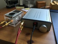
Hi all. A few days ago I finished my whammy. It was a great success, thanks to all the support I’ve got from you guys. Thank you all.
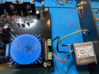
I used the parts-kit from DIY-store which contains very good quality parts. The only thing I changed is the headphone jack. I used a Neutrick-jack which I had on stock. It’s insulated from the chassis. The chassis is the Hammond anodyzed aluminium-chassis. It perfectly fits the PCB.
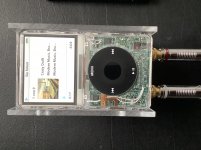
I did not install the input-coupling-caps because the source already has some very high quality Mundorf-caps (Mcap EVO oil 22uF). It is a modified Ipod classic. The output of it’s DAC goes directly to the caps. You can see it on one of the photos. I first tried the stock opamp TI RC4580. Acceptable sound, almost no noise. Then I changed to the Burson V6 vivid. And this one is just outstanding. Now, after 80 hours of burn-in, even better. Its maximum voltage is 16.5 and I measured 16.3 at the relevant pins. It only becomes hand-warm.
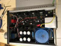
At the beginning I had a little buzz-issue at very high volume settings. I removed the cap between mains-earth (it is now connected directly) and the chassis and used one-point-star-grounding of the chassis and the circuit. After that, it is deadly-quied even on maximum volume. An outstanding headamp. It even drives my demanding HD800 without any problems.
I used the parts-kit from DIY-store which contains very good quality parts. The only thing I changed is the headphone jack. I used a Neutrick-jack which I had on stock. It’s insulated from the chassis. The chassis is the Hammond anodyzed aluminium-chassis. It perfectly fits the PCB.
I did not install the input-coupling-caps because the source already has some very high quality Mundorf-caps (Mcap EVO oil 22uF). It is a modified Ipod classic. The output of it’s DAC goes directly to the caps. You can see it on one of the photos. I first tried the stock opamp TI RC4580. Acceptable sound, almost no noise. Then I changed to the Burson V6 vivid. And this one is just outstanding. Now, after 80 hours of burn-in, even better. Its maximum voltage is 16.5 and I measured 16.3 at the relevant pins. It only becomes hand-warm.
At the beginning I had a little buzz-issue at very high volume settings. I removed the cap between mains-earth (it is now connected directly) and the chassis and used one-point-star-grounding of the chassis and the circuit. After that, it is deadly-quied even on maximum volume. An outstanding headamp. It even drives my demanding HD800 without any problems.
Attachments
I meant not „quied“ but „quiet“ ;-)
Sennfan,
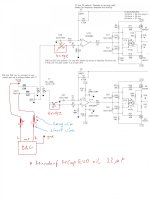
Great work. If you don't mind, can you provide more details on your input setup (DAC output to Mundorf capacitors)? Something like a schematics?
Thanks
PC997,
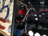
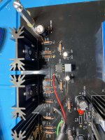
it is so easy, you will not need any schematics. On the photo attached you see the two white ground-wires on the left. Soldered to the iPod ground and the RCA connectors ground directly. On the upper right are the two wires which are directly soldered to the dac-chip’s L and R output. I removed the original SMD- caps. Pins, of course, depend on the dac‘s spec. The mundorf EVO are bipolar but mundorf recommends to solder the short wire to the dac. So I did. The long wire is soldered to the RCA connectors. And from there via NF cable to the whammy. That’s all.
it is so easy, you will not need any schematics. On the photo attached you see the two white ground-wires on the left. Soldered to the iPod ground and the RCA connectors ground directly. On the upper right are the two wires which are directly soldered to the dac-chip’s L and R output. I removed the original SMD- caps. Pins, of course, depend on the dac‘s spec. The mundorf EVO are bipolar but mundorf recommends to solder the short wire to the dac. So I did. The long wire is soldered to the RCA connectors. And from there via NF cable to the whammy. That’s all.
Attachments
As pfarrell said, post some well-lit, in-focus photos of your build so we can take a look.Looking forward to seeing them.
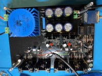
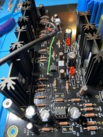
Here are some pictures of the build. Note that on the RCA inputs, I used to have a copper bar soldered across the negatives that was connected to the screw on the chassis via the capacitor but I removed that yesterday when trouble-shooting. It has no effect on the lack of input audio/hum. Also note that the green block connectors on the input have full continuity to the input resistors. I just did it that way so I could easily disconnect the rear chassis plate (RCAs/inlet AC/etc...) if I needed to get into the chassis later (which I am now glad I did). As I said above, I've tested all of the resistors, caps and specified voltage test points that I could find on the forum, build-guide and schematic and everything is within a reasonable tolerance.
Attachments
I do not want to turn this thread into an amp rolling discussion. If anybody feels I am doing this please say so and I will stop.
I hope this is useful for somebody (my initial choice of the op amp for Whammy was inspired by reading people's opinions here).
The direct reason for this post is a package which arrived this week from Passive420.
It contained a box with some delights. These include
1. metal cans opa627 on brown dog single to dual
2. LT1361
3. OPA604
4. LT1028
5. and metal cans LME49710
Today I made some time to do some swapping. My benchmark nowadays is Burson V6 classic (as some of you might have noticed), AD823 before.
Here are my initial imressions.
I started with opa627. Wow, very close to Burson, Burson has somewhat warmer sound a notch more live like. Then LT1361, very very good. Then I listened to opa604 which I liked less.
I could not get LT1028 working. I removed all compensation caps as Passive suggested but the amp was still oscillating.
In fact these are all very fine chips and while you can hear differences between them it is really hard to say which one is better. Might be a question of personal preferences.
After some swapping I decided that OPA627 is the one to leave in Whammy to see how I like in the longer run. As I said I prefer Burson, but I want to see how much I would miss if anything when opa627 is playing on a daily basis.
Apologies to those who would prefer blind abx tests...
I've seen a couple of posts with pictures of a red 8 pin standoff for the opamp that looks like its there for easy swapping of opamps. Can someone please post the make/model of what they are using?
Here are some pictures of the build
Can't really see from your photo and this may sound really obvious but are the output wires from the Whammy connected to the unswitched side of the headphone jack?
Here are some pictures of the build.
This may sound nit-picky but, looking at your board, the soldering seems a bit inconsistent. Perhaps reflow all solder and see if the issue goes away?
Can't really see from your photo and this may sound really obvious but are the output wires from the Whammy connected to the unswitched side of the headphone jack?
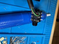
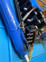
The 3 outputs are only connected to one side of the socket. I've attached pictures to show this. The Nutrik connector appears to disconnect the pins on the opposite side when plugged in, but has them connected when not in use.
That is how its shown in the build-guide too:
"WHAMMY" Pass DIY headphone amp guide
I verified continuity from the ground side of the 1/4 headphone jack to negative on the other side of the connector to the "ground" on the input of the board.
Attachments
This may sound nit-picky but, looking at your board, the soldering seems a bit inconsistent. Perhaps reflow all solder and see if the issue goes away?
Thanks for the suggestion. I actually had some cold solder joints on the PS when I first built it, and had to re-flow some there. That might be my issue now as I was overzealous on the "resistor installation" phase and mistakenly installed the resistors for the non-LED reference. Removing them was a bit of a challenge, but the voltages and continuity checks across those points showed they were ok so I assumed they were ok.
thomasnadeau - Where do you have input ground connected to the PCB?
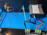
Do you mean neutral or chassis/earth ground? The earth ground is connected to the chassis back panel screw as suggested in the build guide. I am not showing the capacitor there as I removed that earlier thinking it might be the culprit and just haven't put it back in.
Should I have connected the ground point of the board to this point? The build guide does not mention any connection of the board to the input ground except through the shield of the input connector that is attached to the RCAs' negative (which is connected to the chassis ground via the cap). The headphone connector is plastic, so it is isolated from the chassis. The board itself is on standoffs that do not connect the ground plane to the chassis, but I have not tested it in the actual enclosure yet (its sitting on a silicone/anti-static mat on my bench).
If it's red then undoubtedly it's the SparkFun model BOB-13655. Have a quick google to find ordering information including a color photo.
Yes that was it. Thanks for the pointer. It looks like both Digikey and Mouser have it. I'll post the references here for others to easily find it:
Digikey:
BOB-13655 SparkFun Electronics | Prototyping, Fabrication Products | DigiKey
and Mouser:
BOB-13655 SparkFun | Mouser
Should the -ve on the RCAs be connected directly to the Ground stud.
If you look at the 6L6 build guide on page 1 of this forum, isolated RCA grounds are connected to chassis ground only via an RF bypass capacitor. This works for my build with no hum or buzz. Intrinsic unit safety is not an issue because the transformer is double insulated and the possibility of transformer primary connections (pins and pads) on the PCB bridging to any other circuit traces is very minimal. I'd say, so minimal that even if you were foolish and built this without a fuse and the primary traces burned up, they would not connect to anything else.
Now, if you connected something to the Whammy inputs that had dangerous voltage on its RCA shells, it would be carried through to the output jack "ground" and possibly be fatal, depending on cable and headphone construction. If that is a concern, or if you are concerned about the Whammy PCB or transformer or any other aspect of your construction, take a look at some of the grounding schemes floating around out there and connect circuit ground to chassis ground using diodes or a bridge rectifier bypassed with a 10 ohm resistor or a 10 ohm thermistor. Even a 10 ohm CL-60 by itself should provide enough of a pathway to chassis ground, even while the fuse is blowing if the source is catastrophic.
That said, there are a lot of commercial components out there that have continuity from the input connector shells to the output shells and are powered by external wall warts. They don't have a chassis grounded to the AC line ground. They could pass dangerous voltage/current from inputs to downstream components as well. But it would not be that commercial component or the Whammy's responsibility if the device connecting to it is dangerous.
Last edited:
The build guide does not mention any connection of the board to the input ground except through the shield of the input connector that is attached to the RCAs' negative (which is connected to the chassis ground via the cap).
I think that's your problem. You don't have the RCA grounded to the input of the amp. The signal circuit is incomplete. The RCA grounds (tabs) go to the cable's shield and then the shield is connected to the ground hole (which is inexplicably unlabeled on the PCB...) at the input. Photos and captions from this thread, post #3 -
Input at RCA jacks.
Input at PCB. In this photo the ground wire is mostly hidden by the jacketed cable.
- Home
- Amplifiers
- Pass Labs
- "WHAMMY" Pass DIY headphone amp guide