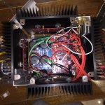
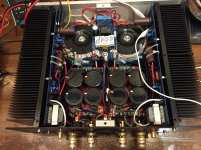
As far as heat dissipation the 4U is more than adequate. As soldersober said it will be tight installing the Salas inside but not impossible. You can probably install it on top of the PS with some tall standoffs. At least that is what I have done with the BA-3 board on the BA-1 and F4 I own. Yes I installed a BA-3 pre inside my F4, preferring it better that way.
Thanks, everyone, this is very helpful.
Do you happen to have some inspirational pictures of the inside?
As far as heat dissipation the 4U is more than adequate. As soldersober said it will be tight installing the Salas inside but not impossible. You can probably install it on top of the PS with some tall standoffs. At least that is what I have done with the BA-3 board on the BA-1 and F4 I own. Yes I installed a BA-3 pre inside my F4, preferring it better that way.
Do you happen to have some inspirational pictures of the inside?
I just realized the entire DCG3 with the DTSB boards and the transformers for the pre amp will fit on the front panel of 4U chassis.
Since you don't need the heat sinks for DTSB (mount the FET's on the reverse, front panel as heat sink), the whole thing will take very little floor space
Since you don't need the heat sinks for DTSB (mount the FET's on the reverse, front panel as heat sink), the whole thing will take very little floor space
I just realized the entire DCG3 with the DTSB boards and the transformers for the pre amp will fit on the front panel of 4U chassis.
Since you don't need the heat sinks for DTSB (mount the FET's on the reverse, front panel as heat sink), the whole thing will take very little floor space
Excellent idea
4U 4 Me!
(Apologies to Lionel Richie).
The vfet is a really tight fit in the 4u. I'm sure you can get it all in there, but getting to some things will be awkward and frustrating. If space isn't a concern, where the amplifier will be sitting, a 5u will give you a lot more room to work. Which can save a lot of frustration 
My Vfet in a 4u case with Antek AS4222 and single peter daniel power supply board. Capacitors are 50 volt. There is probably 2 inches of usable space in between the power supply, vfets, and the top panel:
https://1drv.ms/i/s!AtUqSzQhRd9Xgb5YO18IFBuW23dcPQ
Should have added: The transformer goes right up to the edge of the PCB, probably 3/4" away, and the 50 volt capacitors are the tallest things in there. They are taller than the front end heat sinks on the pcb's
Last edited:
- Status
- This old topic is closed. If you want to reopen this topic, contact a moderator using the "Report Post" button.
- Home
- Amplifiers
- Pass Labs
- 4U or 5U Chassis for SONY VFET/Salas Integrated Hybrid

