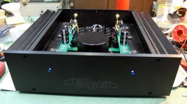
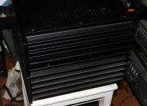
while I was sorta waiting to get it on temp , listening tuner , solving drek connection on Tanns , my friend Woland newly acquired ;
bass connection will be ditto on original soldering eyelets , while I moved squawker wires to newly made solder pads , mounted on one spider ring bolt
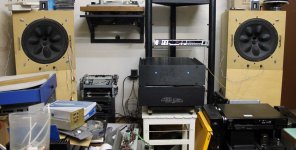
later I switched to my workshop CD-DAC as source
bass connection will be ditto on original soldering eyelets , while I moved squawker wires to newly made solder pads , mounted on one spider ring bolt
later I switched to my workshop CD-DAC as source
Attachments
Last edited:
in more words ...... something as bstrd of SIT-1 and M2 
as I wrote on Baby DiyA - from all sane FW amps (most of them I had on my handy chipboard test-bed, either mono or stereo ) , Babelfish J2 is the best , while M2 is definitely dearest
in my world , those two aren't mutually exclusive
SIT-1 , SIT-2 and , I strongly believe, now - DEFiSIT - are excluded from list of sane FW amps
We've seen everything from Pa ....... some amps are all wit , some are all quirk ..... but those 3 are Demonstration of Force
pretty much as XS Bigguns in PL Coral , but I didn't had opportunity to squeeze these on my chipboard
")
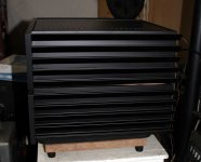
back to little one
words
Spooky
Just Right
as I wrote on Baby DiyA - from all sane FW amps (most of them I had on my handy chipboard test-bed, either mono or stereo ) , Babelfish J2 is the best , while M2 is definitely dearest
in my world , those two aren't mutually exclusive
SIT-1 , SIT-2 and , I strongly believe, now - DEFiSIT - are excluded from list of sane FW amps
We've seen everything from Pa ....... some amps are all wit , some are all quirk ..... but those 3 are Demonstration of Force
pretty much as XS Bigguns in PL Coral , but I didn't had opportunity to squeeze these on my chipboard
back to little one
words
Spooky
Just Right
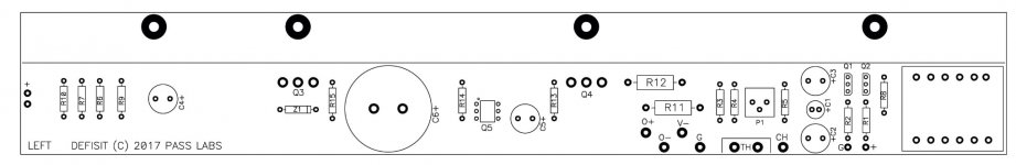
Look it's another DEFiSIT board version : Q5 is probably one optocoupler ??
possible ........ what else 6-legged ?
now even more resembling M2 ...... Papa preparing DEFiSIT for the masses
puzzled - from where you got that pic?
Last edited:
introducing source resistors and optocoupler between gates , allows any specimen of chosen parts to be used in circuit (same as in M2 ) not just painstakingly selected ones , as in DEFiSIT presented on BAF (and here)
edit ....... ha - that means Papa can toss in , all lefties and righties of Pass-SIT-1

.......
if he change name to DEFiSIC , he can use that vagon of SJDP
edit ....... ha - that means Papa can toss in , all lefties and righties of Pass-SIT-1
.......
if he change name to DEFiSIC , he can use that vagon of SJDP
Last edited:

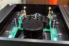
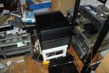
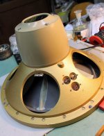
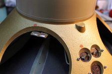
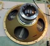
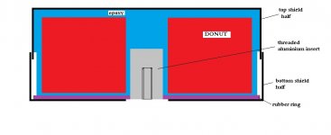
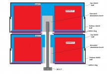
how to stack two potted and shielded Donuts
had two identical ones , with threaded Aluminium insert , for 6mm bolt ;
that's left pic
took one , drilled with 8mm bore through center of insert and all the way , then took 12mm bore , and increased hole on top of top shield half , to prevent any possibility of contact with bolt body, thus no possibility of short circuit
took two rubber rings , for placing one beneath and one in between Donuts
took proper length 6mm bolt , stacked them and that's it
that's right pic
short piece of wire soldered to each of 4 pans , all 4 soldered to one wire , routed to main chassis bolt (back left rubber foot bolt; star washers necessary)
Attachments
Last edited:
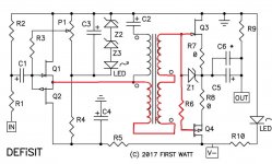
there is input cap too
buffer and xformer are DC coupled , rest of xformer is DC decoupled from GND
gates of JFet buffer are elevated somewhat bellow Ub/2 , so their sources , so entire xformer winding ........ DC coupled to output's gates , so their sources are at Ub/2
reminder : P mosfet demanding gate approx. 4V lower than source , for being able to conduct ; thus entire (red) biasing route need to be at (Ub/2)-4V
Attachments
thx for the drawing
instead of dc coupling the autoformer to the buffer and lifting it off ground the autoformer could have been tied to ground and decoupled from the buffer - just as in the M2. The biasing would then need to happen after the cap, just as it does in the M2.
Here, the biasing happens before the buffer, but doing it this way comes at the expense of an input cap so I suspect there is an inherent advantage. What is it?
.....
Here, the biasing happens before the buffer, but doing it this way comes at the expense of an input cap so I suspect there is an inherent advantage. What is it?
well , I'm the one who is obsessed with DC coupling , but Papa obviously isn't
everything is much simpler , when you decide to use cap or two
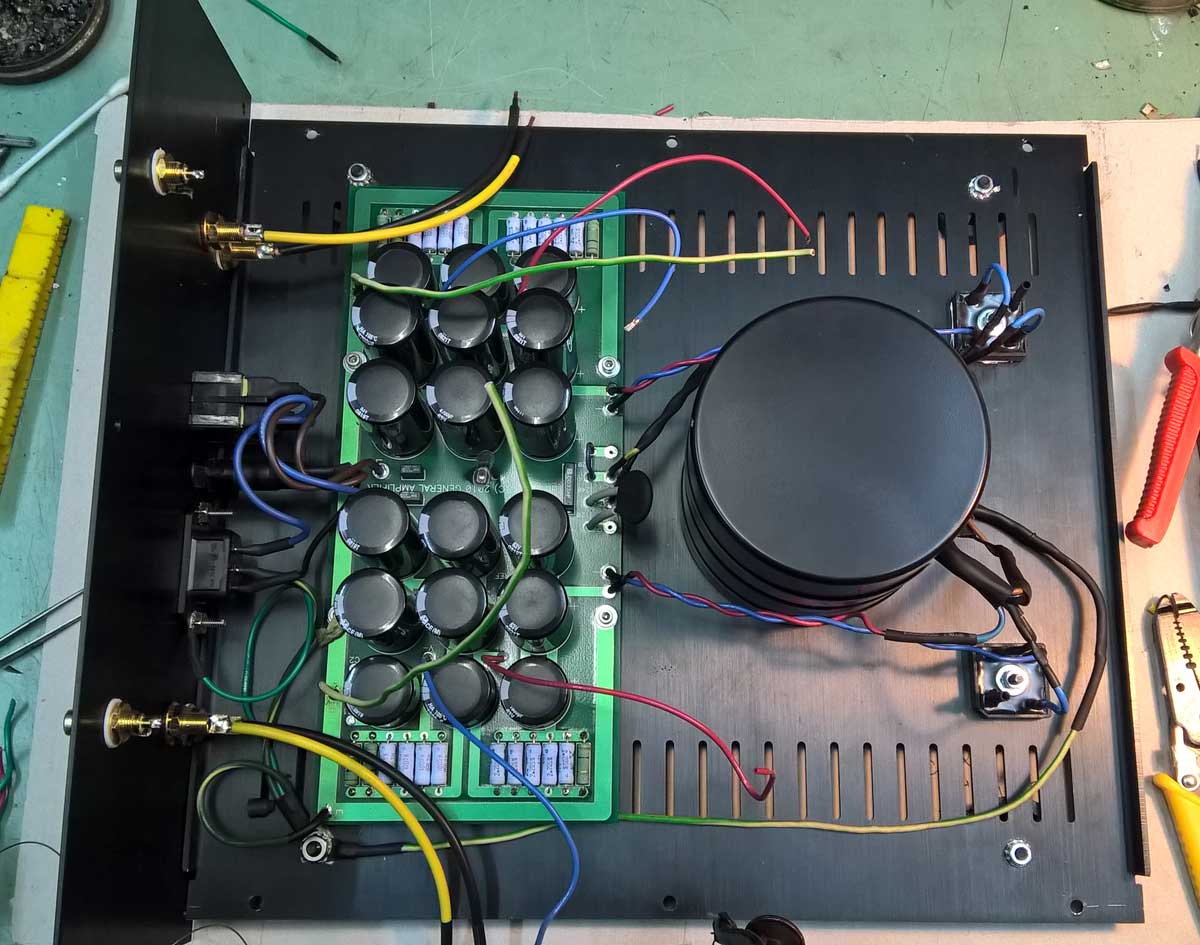
ZenMod are you able to reveal the configuration of the powersupply?
It looks like it might be a variation on the F6/F7 supply.
dunno what will be for production iteration , but this one is CRCRC ; that's pretty much enough ....... we (greedy Boyz) are anyway used to choose our poison , same as size of it
- Home
- Amplifiers
- Pass Labs
- Most Greedy Boy, of them all... or (there is no) DEFiSIT of Papa's Koans