In theory, there is nothing stopping you from making a choke loaded bipolar follower.Would it be possible to build a Mofo With Npn transistors?
The things you need to solve are:
Bias circuitry.
Potentially lower input impedance.
Start a thread with your Idea. sounds fun.
HTH
Would it be possible to build a Mofo With Npn transistors? A Bifo?..
Here's choke-loaded bipolar from 1966. As DougL hints, it wants a second stage to get a decent but still-low input impedance (and there must be an input cap). The way the NFB works, it is more current source than voltage source (low damping); but some folks like that too. This form does have decent voltage-gain (~~1Vrms in for full output). You could do NPN Darlington and get voltage-source and maybe 5k Zin but need 10Vrms drive.
Attachments
What are the favorite output caps you have used? (make and part number)?
I imagine this cap imparts a good amount of character on the sound.
I've just gone through the 219 pages and have seen mention of Vishay/BC, Mundorf, Panasonic and Nichicon. Perhaps I have missed posts comparing the merits of different caps. I'm about to buy parts and am curious.
This is a great thread. Thank you all.
I am very happy with my MoFo's. I use Jensen audio grade caps. 2x6800 uF parallel. 5 Hz in 8 ohm was no problem. Caps are not cheap. About 100 USD each. ESR very low. About 7 mOhm as far as I remember (probably for the parallel pair). The impedance stay < 10 mOhm up to 100.000 KHz. Probably the reason they call it "audio grade". Caps has low inductance.
Attachments
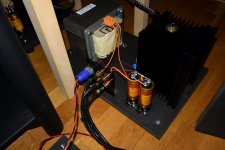
Thank you! ….I am now using M2X amps. It was my intention with MoFo to try to short the output caps as with 3A bias and 73 mOhm choke DC is about 0.2 V which the 4" voice coil in the woofer can handle. But I forgot to make that experiment. Now these MoFo's with PSU's takes up a lot of space!
Attachments
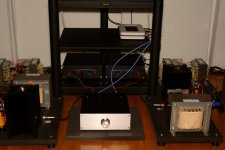
Yes, around 20 kg each. The coil is 12.5 mm2 square wire. Should be able to handle 28 Amps of current. I was suggested from the transformer company a bigger option if I wanted to go down to around 35 mOhm DC resistance. It was an IU core type choke and weight was 55 kg. Then making MoFo without an output capacitor was a real option.....I think.
Good News/Bad News
Thanks again to everyone here for helping me on my journeyman's quest in audio electronics. Thanks to Vunce for providing PCBs. Greatest thanks and prayers to MRothacher for a simple and obviously enduring design! I'm up to page 106 in the thread; apologies if this has been addressed in the last half.
I finished my MoFo's yesterday, built to spec., using the Hammond 193T inductors, powered by twin 19V/4.74A laptop power supplies. Bias across the chokes I measured at 1.03V and 1.04v. I used 3" x 10" heat sinks.
For source audio, I used the 'phone output of my 20-odd year-old Boston Acoustics (BA265). Because it has a volume knob. Speakers are Sony SS-U610 (3-way; 12" woofer, 2 caps for a 'crossover')
Sounded lovely for about 2 hours. Then I went to bed. I left the amps on, thinking this was OK for burn-in, but this morning the right channel was no longer producing heat, and there was a periodic 'thump'. I immediately pulled both power supplies from the wall.
On the right channel, G-S resistance across the mosfet in situ is ~8.5R, compared to 58.3KR in the left channel. That looks to me like I need to replace it.
Can anyone suggest other items to check?
Kind regards,
Drew
Thanks again to everyone here for helping me on my journeyman's quest in audio electronics. Thanks to Vunce for providing PCBs. Greatest thanks and prayers to MRothacher for a simple and obviously enduring design! I'm up to page 106 in the thread; apologies if this has been addressed in the last half.
I finished my MoFo's yesterday, built to spec., using the Hammond 193T inductors, powered by twin 19V/4.74A laptop power supplies. Bias across the chokes I measured at 1.03V and 1.04v. I used 3" x 10" heat sinks.
For source audio, I used the 'phone output of my 20-odd year-old Boston Acoustics (BA265). Because it has a volume knob.
Speakers are Sony SS-U610 (3-way; 12" woofer, 2 caps for a 'crossover')Sounded lovely for about 2 hours. Then I went to bed. I left the amps on, thinking this was OK for burn-in, but this morning the right channel was no longer producing heat, and there was a periodic 'thump'. I immediately pulled both power supplies from the wall.
On the right channel, G-S resistance across the mosfet in situ is ~8.5R, compared to 58.3KR in the left channel. That looks to me like I need to replace it.
Can anyone suggest other items to check?
Kind regards,
Drew
Last edited:
I have built the large MO FO with the Hammond 193v chokes and biased at 2.5 volts and using the 24v supplies.
Looking at a 1000hz sine wave signal on the output (loaded with 6 ohm resistor) I get 23.5 volts positive peak to negative peak before clipping. The Negative peak clips first.
Does that sound right?
I notice that I can get higher positive to negative voltage swing if I increase bias. Is the above mentioned 23.5 voltage swing enough??
Thanks
TL;DR so I started over.
Your max symmetrical, undistorted output current, peak to peak, is 2x your bias current. Your max RMS output current is therefore 0.707x your bias current.
At 6 ohms, your 2.5A peak output requires only a ~15V peak. You have 24V. If you want more power into 6 ohms, you need more current, and you may not even need as much as 24V. However, if your speaker is 6 ohm min and has rising impedances elsewhere, you will need more voltage rail to reach your max current and 24V may be needed. 37 V with a 2.5A bias is optimal for a 13.8 ohm load - into 6 ohms, it delivers no more power before clipping than 18 volts would - literally burning twice the idle power for no more output power, because the bias current is currently your limiting factor not the voltage.
The MoFo-like device I listen to daily has a 15V rail and idles at 2A; works great for a 4-ohm HF driver without burning a lot of extra power. I recently dropped from 24V to 15V with no reduction in delivered power.
Don't conflate the 24V rail with your observed 23V peak-to-peak output. From a 24V rail, you should be able to swing peak-to-peak more than that. This is because the energy stored in the inductor's magnetic field allows negative swings. I think your p-p amplitude is lower than it should be, and that you are correct in thinking that more bias is to your benefit.
Because you have measured peak-to-peak of around 23 volts, are loaded with 6 ohms, and you are clipping at about 11.5 volts peak, you are clipping at about 1.9 A peak. Since you have a 24V rail, you aren't anywhere near close to running out of voltage swing. It thus seems likely that you are biased at a little less than 2A, or else that your resistance is a bit less than 6 ohms, or maybe some combination of both. It is at this point that I would probably be double-checking my measurements and the gear with which I made them, just to satisfy myself that I'm not chasing ghosts.
Question: are you sure that it's the MoFo clipping, and not the preamp? As there's no voltage gain in MoFo, you have to be able to swing a pretty big waveform into MoFo to get its full power out. If your preamp won't deliver 42V p-p swing, neither will your MoFo. The fact that you saw more swing with increased bias suggests that it's not the preamp clipping, but it's worth checking that as well.
Thanks rco3
The pre amp is not clipping...I have checked that separately...My skills with an oscilloscope are not great...and the calibrate function isn't working...so the scope probably isn't too accurate.
Your answers are most instructive...I am concluding that my MOFO is built correctly...and I will be hooking it up to speakers pretty soon...
It sure gets hot
> It sure gets hot
Extra (wasted) heat when voltage and current are not in proportion to the load impedance.
A 24V DC supply should support almost 48V peak-peak output (a good 40Vpp). If you are getting 23Vpp loaded, your supply is more than you need. The extra Voltage is just waste heat.
6 Ohms suggests 24VDC at 4 Amps (96W dissipation!) for ~30W out, or 18V @ 3 Amps (54W diss) for ~~17W out. Laptop supplies with 19V output look like a good choice for 6r loads.
Ok guys, hear me out on this one...
I recently finished my ACA kit, I love the sound and it has given me some more experience in building amps. Now I've returned to the idea of building a MoFo with an input transformer as discussed earlier. My preamp doesn't have enough gain to drive the MoFo on its own to any reasonable power level.
Would it be possible to take the B1 buffer circuit, without the volume control, connect it to the primary side of an Edcor PC600:15K line transformer and have the secondary connected to the MoFo's input? I think the B1 could be powered from the same 19v supply for the MoFo, or maybe the 24v version too.
Is it possible to estimate the input impedance of the B1 buffer? It would have a 1M resistor in parallel with a series 1K resistor on the input.
These topics were sort of covered earlier, I'm just trying to figure out the details.
Ok guys, hear me out on this one...
I recently finished my ACA kit, I love the sound and it has given me some more experience in building amps. Now I've returned to the idea of building a MoFo with an input transformer as discussed earlier. My preamp doesn't have enough gain to drive the MoFo on its own to any reasonable power level.
Would it be possible to take the B1 buffer circuit, without the volume control, connect it to the primary side of an Edcor PC600:15K line transformer and have the secondary connected to the MoFo's input? I think the B1 could be powered from the same 19v supply for the MoFo, or maybe the 24v version too.
Is it possible to estimate the input impedance of the B1 buffer? It would have a 1M resistor in parallel with a series 1K resistor on the input.
These topics were sort of covered earlier, I'm just trying to figure out the details.
for unipolar supply, look at first B1(just N polarity JFets) iteration and then you can use either 19 or 24V without changes ; take care to not use limiting output resistor ( was 1K in first one)
for proper wiring of Edcor = look at M2 threads
regarding Rin- series resistor is usually much smaller than that one shunting gate to "gnd" , so that bigger one (then) dominates
so , Rin is in range of 1M
if you have more dilemmas , make some effort and post schematic of you r intended combo . MS Paint or any other small proggy is good enough for editing small schematics
- Home
- Amplifiers
- Pass Labs
- Build This MoFo!