Ding, ding, ding!!! You win Steve! It’s a BA3, but not just any BA3. This particular project was procured from none other than 6L6 himself. I feel proud to have a piece of diyAudio build guide history as part of my project. Thanks again Jim!!!
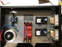
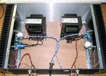
So here’s the mock-up of where everything will live basically. I still need to fine tune the position of the MoFo boards and figure out the left to right to allow for the selector switch and attenuators rods. Coming together we’ll so far though.
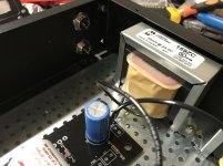
I measured my chokes tonight and they are both coming out at about 42mH. The 159zc are spec’d at 60mH with a 15% tolerance. Do I have a garbage LCR meter or does the inductance change depending on current applied and temperature?
So here’s the mock-up of where everything will live basically. I still need to fine tune the position of the MoFo boards and figure out the left to right to allow for the selector switch and attenuators rods. Coming together we’ll so far though.
I measured my chokes tonight and they are both coming out at about 42mH. The 159zc are spec’d at 60mH with a 15% tolerance. Do I have a garbage LCR meter or does the inductance change depending on current applied and temperature?
Attachments
Nice stuff jwjarch,
How are you going to power the whole thing, 2 power transformers?
I'm also in the process of putting a preamp and a big MoFo into the same chassis.
I started a thread in the power supplies section asking about an easy way to power the preamp (requires bipolar supply) and MoFo's, has learnt a few things there.
Last edited:
Pass DIY Addict
Joined 2000
Paid Member
I measured my chokes tonight and they are both coming out at about 42mH. The 159zc are spec’d at 60mH with a 15% tolerance. Do I have a garbage LCR meter or does the inductance change depending on current applied and temperature?
Precise measurement of a choke will depend, precisely, on the frequency that your meter uses to measure it. Inexpensive meters just measure and don't indicate what frequency is used - these probably use DC current to measure. More expensive meters will allow you to select from a small range of AC frequencies with which to measure. Super precise measurement requires an even more sophisticated approach with more equipment...
I think you'll be pleased when you are finished with your BA-3 & MoFo combination - mine sound very nice together!
Beautiful work Jwjarch! Super that it fits all in 2U! Outstanding form factor, albeit with some nifty CPU coolers hanging out the top. Sort of Mad Max look in a way.
Stay tuned for the Wayne's BA 2018 preamp module for the Yarra (or stanalone) as a preamp. I just got the verification build PCBs yesterday. Looking forward the hearing that and how it sounds with my MoFo as well.
The WBA18 is the one on left:
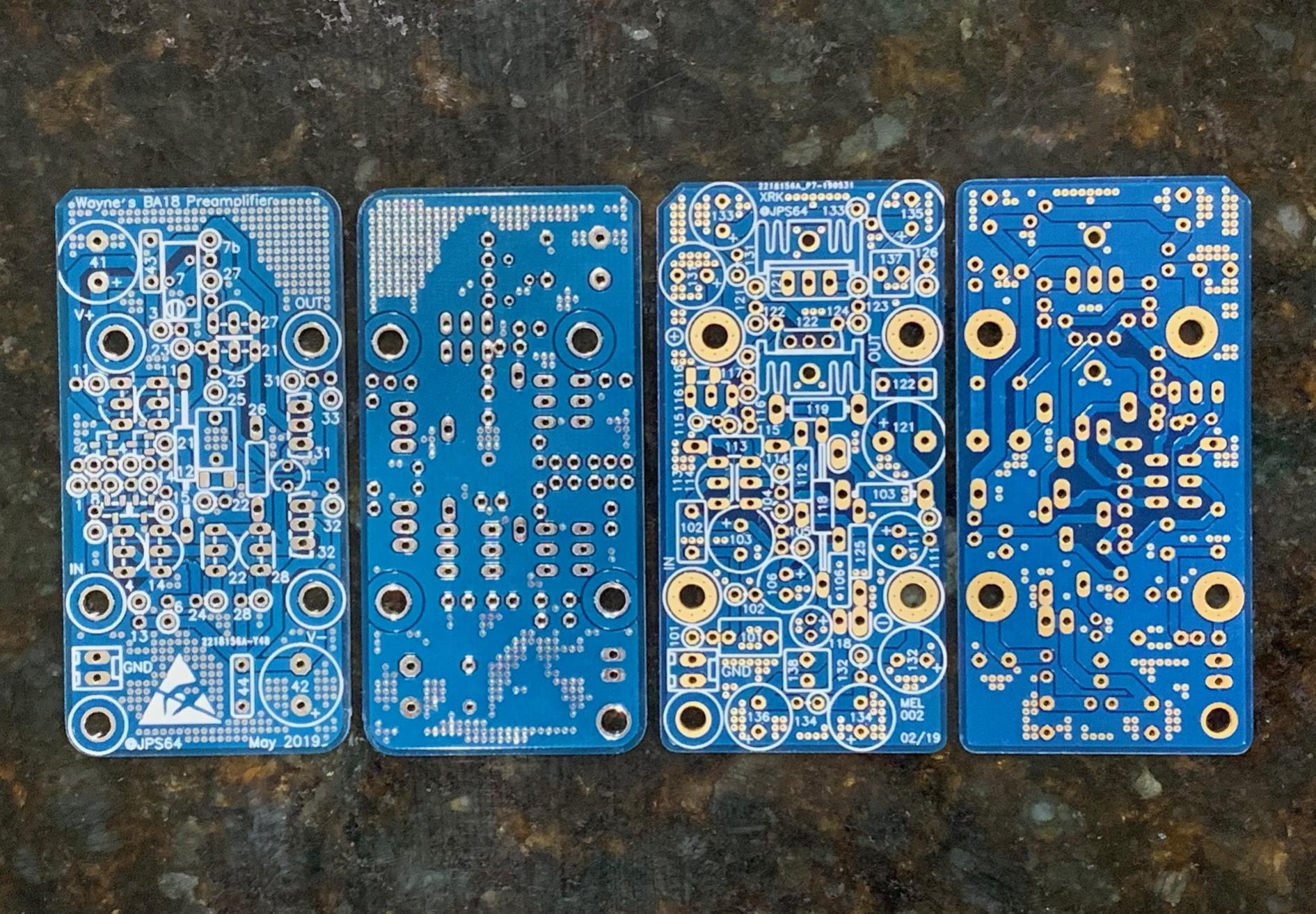
I see you are using the nifty Prasi SMT Cap Mx board for powering the BA3 - those work really well.
I use the Dayton DATS v2 woofer tester in LCR mode and it gives inductance as a function of frequency - nice tool.

Stay tuned for the Wayne's BA 2018 preamp module for the Yarra (or stanalone) as a preamp. I just got the verification build PCBs yesterday. Looking forward the hearing that and how it sounds with my MoFo as well.
The WBA18 is the one on left:
I see you are using the nifty Prasi SMT Cap Mx board for powering the BA3 - those work really well.
I use the Dayton DATS v2 woofer tester in LCR mode and it gives inductance as a function of frequency - nice tool.
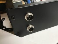
Thanks EmeryBB! I'm going to use the toroid (Antek AS-0520) along with a Prasi SMT Cap Mx board (good call X!) for the BA3 and VSPS dual rail supplies. The MoFo boards will each get a 19.5v, 90W HP laptop power supply. I already modified the cords on the HP supplies to accept the 3 pin aircraft type connectors you see in the photo. I read through your thread in the power supply forum. Interesting initial approach. I didn't want to try and power everything off of the same transformer so I went with the toroid and laptop SMPS's. Good luck with your build!
Eric, thanks for the measurement explanation. That makes total sense. There are too many variables and not always enough standardization of measurements, especially when it comes to audio, i.e. amplifiers rated at a million watts when measuring a millisecond peak wattage at a 1ohm load. Looking forward to hearing this combo sing as well!
Thanks X! I definitely wanted to show off these coolers. They're just too nice to hide inside a case. These Prasi CapMx boards are great! I know they aren't technically a regulated supply though so I hope that doesn't pose any issues with the BA3. The VSPS has onboard SREG using LM7812 and LM7912 so no issue there. Great tip on the DATS! I have it on my birthday wish list already.") Also need it to measure some drivers and get more serious about speaker building.
Also need it to measure some drivers and get more serious about speaker building.
I still haven't gotten much feedback on using 159zc's in parallel. Or would it be better to use them in series? Either way it halves the current that each would see, giving me 4A capability for each channel in theory. In parallel they would be 30mH at 350mOhms resistance. In series, 120mH at 1.4Ohms resistance. I'd like to run with 24v supplies eventually. Pro and cons of this scenario?
Eric, thanks for the measurement explanation. That makes total sense. There are too many variables and not always enough standardization of measurements, especially when it comes to audio, i.e. amplifiers rated at a million watts when measuring a millisecond peak wattage at a 1ohm load. Looking forward to hearing this combo sing as well!
Thanks X! I definitely wanted to show off these coolers. They're just too nice to hide inside a case. These Prasi CapMx boards are great! I know they aren't technically a regulated supply though so I hope that doesn't pose any issues with the BA3. The VSPS has onboard SREG using LM7812 and LM7912 so no issue there. Great tip on the DATS! I have it on my birthday wish list already.
Also need it to measure some drivers and get more serious about speaker building.I still haven't gotten much feedback on using 159zc's in parallel. Or would it be better to use them in series? Either way it halves the current that each would see, giving me 4A capability for each channel in theory. In parallel they would be 30mH at 350mOhms resistance. In series, 120mH at 1.4Ohms resistance. I'd like to run with 24v supplies eventually. Pro and cons of this scenario?
...using 159zc's in parallel. Or ... series? Either way it halves the current that each would see....
No. All parts in a series circuit get the same current.
3A in 0.3 Ohms (parallel) gives 1V of DC drop which should be acceptable for bias stability.
Pass DIY Addict
Joined 2000
Paid Member
Keyword search “microwave oven transformer md803” They measure about 65mH and 0.5 ohms dcr. They are air gapped and good for about 10 A.
XRK: Have you measured any other MOTs? I see lots of interesting variations of these transformers: MD-803 vs MD-903 prefix, AMR vs AMS suffix. Just wondering if you have any ideas what these differences in model number actually mean? They all seem to be from 1000-watt rated ovens...
...variations of these transformers...
It is hard to generalize about iron-core windings.
However if the inductance is low, it would be a heavy load on the intended 120V/230V wall-power.
If the resistance is high it would get hot delivering the rated 1,000+ Watts to cook your food.
So there can't be any huge difference between the several models.
120V versus 230V should be a clear difference. I'm thinking most work has used 120V jobs, but some report 230V lumps.
Basically we are using a $300 part for a $30 chore, BUT these over-size parts are cheap or free, so we use a 1KVA part for a 20 Watt job.
The choke is in parallel of the load (your 16 ohm driver) acting as a HP filter like in a 1st order series crossover.
Based on that you need a choke of around 6 - 7 mH, but with very low DCR, eg. 0.1 ohm would be good, lower even better.
Not sure how possible it is to find such a choke that can also handle the current of the MoFo.
Better approach IMHO would be to use whatever high current, low DCR choke you can find and then fit a cap that sets the HP point, in series with the positive input of the driver.
Calculate the value of the cap as for a 2nd order HPF.
Thanks
Pass DIY Addict
Joined 2000
Paid Member
Fair call on the comparison between the hockey puck and IRFP250
Can someone please explain what the 'hockey puck' is in this case?
Thanks,
werd
- Home
- Amplifiers
- Pass Labs
- Build This MoFo!