Is this Noctua fan referred to by XRK971?
Noctua NF-R8 redux 1800 PWM 80x80x25mm. 4-pin PWM. 1800RPM
https://www.lazada.com.my/products/...hlistcategory.list.31.317e6a74JdJt63&search=1
Hi Kp93300,
No, it is this one: Noctua NF-A8 PWM
NF-A8 PWM
")
I'm a little late to the party but have decided to put together a MoFo project - mainly because I have most of the parts already available but it also looks like fun to work on something so simple. I have PCBs in transit from the DIY Audio store and I've picked up a pair of MOTs for £20, which more or less complete the 'BOM'.
My DACs output around 2V so I know I need to driver stage in front of the MoFo. The completed MoFo will either be used as the amp in a 'spare' room system or for the bass section of a possible two-way OB build (high efficiency 16ohm bass unit, top end, mid/top section will be 15ohm lowther powered by a SE-OTL tube amp)
I'm a fairly experienced amp builder, having put together a number of tube and solid state projects, have a good awareness of safety aspects, but but my talent isn't electronic engineering theory/design so I'll appreciate any help you guys can offer with some basic questions about my plan.
To drive the MoFo I have two already assembled modules left over from previously started projects. These are a Broskie Aikido Cascade, which, as configured below, has a voltage gain of x55 - I think too much for my needs but I'm not yet sure how to adjust the gain of this circuit so some reading of TCJ is likely to be required;

and the other is a Broskie CCDA, which can be easily configured for a voltage gain of between 10 and 50, dependent on the choice of tube and setting a few resistor values;

With 2V available from my DACs I believe I'll need the driver stage to deliver a voltage gain of circa x10, assuming a MoFo power supply voltage of 20V?
Any comments/observations on these driver options?
The main question I have about adopting either the Aikido or CCDA as the driver is how to optimally hook either of them up to the MoFo stage; both have decoupling caps on their outputs whilst the MoFo has an input cap so it feels as though I should dispense with the driver stage output caps and just connect the output to the 'IN' of the MoFo? And, where does that leave the resistor on the output of the driver stages - remove as well? Sorry if this is noddy stuff but I'll be grateful for any assistance offered.
Cheers
My DACs output around 2V so I know I need to driver stage in front of the MoFo. The completed MoFo will either be used as the amp in a 'spare' room system or for the bass section of a possible two-way OB build (high efficiency 16ohm bass unit, top end, mid/top section will be 15ohm lowther powered by a SE-OTL tube amp)
I'm a fairly experienced amp builder, having put together a number of tube and solid state projects, have a good awareness of safety aspects, but but my talent isn't electronic engineering theory/design so I'll appreciate any help you guys can offer with some basic questions about my plan.
To drive the MoFo I have two already assembled modules left over from previously started projects. These are a Broskie Aikido Cascade, which, as configured below, has a voltage gain of x55 - I think too much for my needs but I'm not yet sure how to adjust the gain of this circuit so some reading of TCJ is likely to be required;
and the other is a Broskie CCDA, which can be easily configured for a voltage gain of between 10 and 50, dependent on the choice of tube and setting a few resistor values;
With 2V available from my DACs I believe I'll need the driver stage to deliver a voltage gain of circa x10, assuming a MoFo power supply voltage of 20V?
Any comments/observations on these driver options?
The main question I have about adopting either the Aikido or CCDA as the driver is how to optimally hook either of them up to the MoFo stage; both have decoupling caps on their outputs whilst the MoFo has an input cap so it feels as though I should dispense with the driver stage output caps and just connect the output to the 'IN' of the MoFo? And, where does that leave the resistor on the output of the driver stages - remove as well? Sorry if this is noddy stuff but I'll be grateful for any assistance offered.
Cheers
Last edited:
Comments on driver options:
The CCDA topology looks preferable to me.
The cascade has too much gain that shall oblige you to "destroy" a lot of the input signal.
(Worth reading: CCDA projects with different tubes: shine7.com )
Since the Mofo is a relatively easy load for a preamp, i breadboarded a simple gain stage without follower. If the tube has enough guts, this works quite well.
To make life easy i use tubes with heater voltages of between 18 and 20V.
The SMPS supply of the Mofo also delivers to the heaters of the tube and to a high voltage flyback to produce the B+ for the tube (inspired by two Pete Millet projects...)
How to connect the preamp to the Mofo?
Omit the output cap and the 1M resistor in the CCDA
Since you bought PCBs for the Mofo, it makes sens to populate them. I would use components that can be used for CCDA or Cascade (different voltage ratings required)
For C1 (in Mofo) use a cap that can withstand the B+ of the tube preamp (for instance MKP rated 400VDC)
For R1 use 220k
I think that's it
I used a 6N6P CCDA for my MoFo build.
If you omit the cap on the CCDA and connect to the MoFo, the CCDA Rload resistor will be in parallel with the 200K input resistor of the MoFo.
I used a 1uF cap output for the CCDA connected to the junction of R1, R2, and R3 on the Mofo. I eliminated C1 on the MoFo.
If you do use the CCDA, make sure you use the protection diode for the cathode follower.
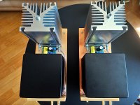
Two brand new MoFos.
Those are 'big' ones.
They were supposed to warm up my apartment during the winter, but I was a bit late with their construction )
I'm considering to diy anodize the heatsinks.
Those are 'big' ones.
They were supposed to warm up my apartment during the winter, but I was a bit late with their construction )
I'm considering to diy anodize the heatsinks.
Attachments
Last edited:

I finally finished the case work - always slow and tedious even if this is an "un-case" (no walls, just a baseplate). Both channels running at 1.7amps provided by a Juma's Easy Peasy cap multiplier which takes 24v from 5amp SMPS down to 19.5v and provides a soft-start for the 22mF//0.22R//22mF CRC before the amp.
Hi xrk, nice job. I'm going to borrow some aspects of your build, particularly the Cap Multiplier/CRC in the power supply. Can you confirm the value of the caps you used in the CRC please - for 22mF do I read 22uF or 22000uF - from the size of the caps and the voltage in use it looks like the latter?
Cheers
Yes, 22mF is same as 22,000uF x 2 caps.
I thought so as 22uF wouldn't seem to make a lot of sense. I think perhaps it's another example of our different understanding despite our shared language as to me mF is the same as uF.
Did you try your power supply without the CRC; in theory the cap multiplier alone should be sufficient shouldn't it?
Cheers anyway.
Pass DIY Addict
Joined 2000
Paid Member
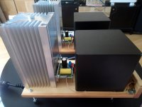
Wow! Those are some pretty large sinks! It looks like you have some fat chokes as well - what bias level are you running? With isolated sinks like that, all you need between your mosfets and the sinks is a bit of thermal goop. This will allow FAR better heat conduction than any thermal pad out there.
Any details on your chokes, or are they covers to hide otherwise ugly looking microwave parts?
Any details on your chokes, or are they covers to hide otherwise ugly looking microwave parts?
what bias level are you running?
Amps are biased for 2.5A. Not daring to go higher as transistors reach 100C on their surface after an hour or so.
With isolated sinks like that, all you need between your mosfets and the sinks is a bit of thermal goop.
Wanted to keep heatsinks electrically isolated from mosfets, but maybe you'r right and I will get rid of thermal pads to knock down the mosfets temp a little, thank you!
Any details on your chokes, or are they covers
They are just steel covers, hide large MOTs, helps with shielding too, just in case.
Strange your mosfet get that hot. I run 3A/26V with about same heatsink. The heatsink get to about 54 C and mosfet a bit higher at the surface (65 C or so). I have placed the PCB so mosfet is at the middle (in height). Maybe this gives a better transfer of the heat...….
- Home
- Amplifiers
- Pass Labs
- Build This MoFo!