No, just the thick gauge primary. It has Faston tabs in it whereas secondary has small insulated female Fastons and skinny wire. Tape off the secondaries and leave alone as they can make HV. In a microwave oven the secondaries make 2300v at 0.5amp when primary is connected to mains.
don't you use the thick secondary that normally powers the filament heater of the magnetron?
-is there a reference on the label of your trafos so that I could try to find the same ones?
The one you are thinking about is just a few turns, hence very low inductance.
Nowhere near what we need for the MoFo.
The primary is what's used in a MOT.
don't you use the thick secondary that normally powers the filament heater of the magnetron?
-is there a reference on the label of your trafos so that I could try to find the same ones?
Look for “MD-803AMR microwave oven transformer” in an eBay or web search. This is the one I use (I have 4 of them). They are about $25ea shipping included when you find a deal.
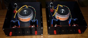
My LCR meter shows approx 65mH and circa 0.5ohm DCR for the thick primary (approx 14ga or maybe 13ga copper magnet wire visible) has Faston tabs. The secondaries are wrapped in fabric insulation - don’t use those as they are very thin wire designed for 2300v and 0.5amp. Whereas the primaries are for about 10amps.
For example:
Microwave Oven High Voltage Transformer MD-803AMR-1, g142 | eBay
The core is made of plates of steel that have two air gaps maintained by their outer edges being TIG welded together with a spacer which is then removed after the weld. The primary can sustain 4-5amps DC and barely heat up maybe to 30C. They appear to work well as you can see that the output swing well above the rail voltage even when running close to 5amps.
If you look carefully at the photo, you will see I have a black and green wire connected to the two Faston tabs on the thick lower windings. The black wire goes to the MOSFET and the green goes to ground. Measuring DC voltage across the MOT gives you the bias current.
Last edited:
Pass DIY Addict
Joined 2000
Paid Member
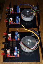
Very smart idea to put the CPU cooler upside down.
XRK: Wow, that's some serious power out of the MoFo! What is the point of mounting the CPU coolers upside down? Does this make them more efficient in some way?
I am using those same MD-803AMR microwave transformers in my build. The microwaves that these transformers come from are rated at 900w (about 7.5A). The primary on mine is wound with 15g solid core wire. The secondary is VERY fine wire and is NOT capable of carrying ANY kind of current that is useful for an amplifier build. I partially stripped the paper that was wrapped around the coils and snipped off all of the secondary leads. The only terminals left are the 1/4" fast on tabs for the primary winding. I figured things would be more safe this way.
Edit: If mounting only a single mosfet on each sink, there is no need for a mica/keratherm/ceramic insulator at all. Just smooth off the surfaces and apply a little bit of thermal paste. This will give the best thermal transfer, but makes your sinks live, so some care is needed.
Last edited:
What is the point of mounting the CPU coolers upside down? Does this make them more efficient in some way?
No reason except for ease of mounting the MOSFET face up. The heat pipes are filled with a sintered metal wick so they work in any orientation, not needed to be "up". As these computers are sometimes placed in tower mode, which would make the heat pipes oriented sideways (on the original Dell chassis that these came in). I don't like my heatsinks to be live - as I mount them on a metal frame etc.
he 230v European version will have more inductance and more DCr ? is-it suitable?
I don't know what the actual DCR would be for the 230v version? Maybe 2x? Probably still would work.
Pass DIY Addict
Joined 2000
Paid Member
lucky you in the states
I'm thinking original voltage is relatively irrelevant for this purpose. While the transformers may have somewhat different design for 120v vs 230v, the transformer only sees ~20v and ~3A in use. You might need to do some extra poking around to find the specs, but do a search on "microwave oven transformer" and see what comes up. Then search on the model numbers of the transformers you find to see if you can map this to the model numbers of the actual microwave ovens that they come from. This will lead you to the power output ratings for the ovens themselves. While not perfect, it should provide some data to work with.
Or, just grab one more or less at random and measure it.
Hey Michael, thanks for bringing this topology back to everyone’s attention. For those that haven’t heard this kind of setup, it can sound believably good, especially considering it’s simplicity. For those that haven’t seen it, here’s my adventures with making this kind of amplifier some time ago. -> My first ever Class A amp.
Hey Michael, thanks for bringing this topology back to everyone’s attention. For those that haven’t heard this kind of setup, it can sound believably good, especially considering it’s simplicity. For those that haven’t seen it, here’s my adventures with making this kind of amplifier some time ago. -> My first ever Class A amp.
Hi Circlotron,
Nice work! Thanks for sharing your build (from 2002) again. Seems that you are getting great efficiency at 50% - impressive as it takes me 150w dissipation for 50w output, so only 33%. Also, was dissipating 100w from your MOSFET with a conventional passive heatsink (which doesn't appear to be all that big) an issue?
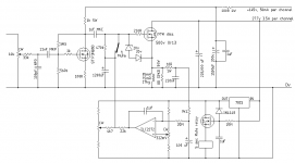
Can you explain what the 2200uF cap tied to the speaker +ve and then the other end tied to the voltage divider from 100v does? It appears to be a bootstrap, and perhaps this is one way you were able to get the higher output without clipping the top?
Thanks,
X
Yeah, it's for bootstrapping. I was trying to get the gain of that first mosfet as high as possible. Eventually used a CCS load as well as bootstrapping and the gain was something like 3000. There was issues with LF instability where the speaker would slowly move to and fro on loud program material.Eventually settled on the cct attached here. Still have the amp sitting in the corner. Hasn't been fired up for yonks.Can you explain what the 2200uF cap tied to the speaker +ve and then the other end tied to the voltage divider from 100v does? It appears to be a bootstrap, and perhaps this is one way you were able to get the higher output without clipping the top?
Attachments
Pass DIY Addict
Joined 2000
Paid Member
From Mike's writeup:
Measure the voltage across the inductor terminals while you slowly adjust P1 upward. The current through the inductor is the voltage you measure divided by the resistance you wrote down earlier. So, the voltage reading you want is your target current times the DCR. For example, if your DCR is .6 ohms and you want 1.7 amps through L1, you’re looking for 1.7 x .6 = 1.02 volts at the inductor terminals.
Alternatively, you can insert a .1 ohm 3W resistor in series with the positive terminal of your PSU and measure the voltage there, e.g. .1 x 1.7 = .17 volts.
I'm running mine at about 19v and 3A, so my sinks get pretty hot.
Pass DIY Addict
Joined 2000
Paid Member
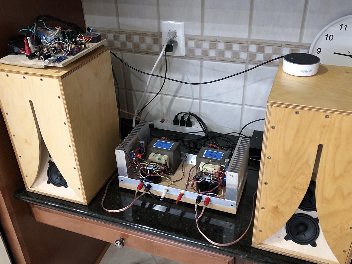
I've been listening to my MoFo & BA-3 combination through a pair of Tang Band 1772s quite a bit lately and I'm just amazed how nice they all sound together! It even makes Pandora through my iPad or Echo sound pretty good. Still can't completely identify what it is that I'm hearing, but I suspect it may have something to do with the second harmonic in each of these devices. Soundstage and vocals are just awesome!
Yes, SE Class A amps have dominant 2nd harmonic distortion with descending higher orders and that is why it sounds pleasing to the ears. The zero global feedback keeps the correct phase relationships, along with single full range driver - so that the soundstage and imaging are very accurate. An ultralow distortion amp with a typical balanced front end and lots of negative feedback will not sound the same beccause of the harmonic profile and phase relationships. Some people prefer dominant third order distortion and lots of negative feedback though. I agree that the MoFo with a fullrange speaker sounds great. It is my daily player in the kitchen with Amazon Dot (Alexa) as source and an Aksa Lender preamp, then 0.53x scale Karlsonator full range speakers with dual 3FE25-16's. Superb combination.
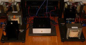
I just finished my BA3-pre with dual mono external regulated PSUs. I use 1m long lab banana cables in the moment for powering the BA3-pre (will make some dedicated cables later) but even then the setup is silent with no noise or hum. This also shows that twisted pairs can be quite good as signal cables. I was able to put two gnd wires in the same hole on the BA-3 pre PCB. BA3-pre works perfect with MoFo! ….a nice pair!
I have not played with P3 yet so P3 is just in the center position. Compared to when I use the pre in NAD M3 music is more dynamic and room definition better.
I have not played with P3 yet so P3 is just in the center position. Compared to when I use the pre in NAD M3 music is more dynamic and room definition better.
Attachments
Pass DIY Addict
Joined 2000
Paid Member
XRK: I've seen that image before and your kitchen setup tells me that you don't have any small children in the house ") . Our youngest is now 11 so she's not really a worry around my electronics anymore.
. Our youngest is now 11 so she's not really a worry around my electronics anymore.
MEPER: I'd like to see some details about the regulator you are using for your BA-3. I built a set of regulators as indicated here Using 3-pin regulators off-piste: part 4 but they don't seem to perform as promised. My noise floor for the PSU seems to clock in somewhere near the -75bB mark...
. Our youngest is now 11 so she's not really a worry around my electronics anymore.MEPER: I'd like to see some details about the regulator you are using for your BA-3. I built a set of regulators as indicated here Using 3-pin regulators off-piste: part 4 but they don't seem to perform as promised. My noise floor for the PSU seems to clock in somewhere near the -75bB mark...
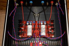
Those regulators are Pete Millett's designed primary to be used as 5V filament supply for e.g. 300B tubes. It was also my intention but I found another solution. Then I asked Pete for recommendation for component values if I wanted about 24 VDC (I have adjusted my for 26.5 VDC) so I run -+ 26.5 VDC.
Regulated DC filament supply
It is based on a 1084 regulator. C3 is interesting as it will suppress "noise". In the application notes for 1084 it is described down in the last sections…..and it seems Pete has read it all
This was the suggestions from Pete for component values when voltage is raised from 5 to e.g. 24 V:
"To keep power dissipation in limits, you should change R3 to 270 ohms. R1 + R2 would then need to be about 5k. You could make R2 4.7k and R1 (the pot) 1k. R4 should also be 5-10k.
You need to use caps with a high enough voltage rating, the biggest that fits is good, probably 2200uF 50V on the input and 100uF 35V on the output."
I think it is a straight forward design around a standard regulator but with all the small tricks to make it as clean as possible. I think the layout of the PCB and the compactness has something to say also. 500 mA is not problem but at 1A the heatsink temp is too high so it is low current PSU and also the amount of on board caps are limited. Perfect for preamps.
Attachments
XRK: I've seen that image before and your kitchen setup tells me that you don't have any small children in the house . Our youngest is now 11 so she's not really a worry around my electronics anymore.
Actually have a 6yr old who knows all about electrical safety and even about electronics and amps already, and he has even soldered his own F5.
The MOFO is nice in that only 24v safe voltages. Heatsink is 55C so hot tot he touch but not burn without time to pull hands back.
- Home
- Amplifiers
- Pass Labs
- Build This MoFo!