what is the best N Mosfet for MoFo?
The highest YFS for lowest input capacitance at the working conditions I=2A U=15V
Found the
FQP20N06
FQP30N06 16 / 900pF
FQP33N10
bur their YFS are measured at higher current (more than 10A)... at 2A they are lower
In the paper from MR I think it was concluded that IRFP250 was the best choice….…..
"You could substitute other MOSFETs, the old favorite IRFP240 for example, but the IRFP250 is just about optimal here, and they’re dirt cheap. I know some of you might want to experiment with Q1. I tried lots of other parts. I tried fancy, expensive parts from Cree and they did not have lower distortion. I also tried obsolete parts from Semisouth and Fairchild and they had [FONT=Arial,Arial][FONT=Arial,Arial]slightly [/FONT][/FONT]better distortion performance, but they’re unobtanium and of dubious merit here anyway."
Marconi
if you like to experiment i would suggest the FQA Serie.
A robust, for my own little opinion, good playing one FQA40N25.
FQA40N25 ON Semiconductor | Diskrete Halbleiterprodukte | DigiKey
if you like to experiment i would suggest the FQA Serie.
A robust, for my own little opinion, good playing one FQA40N25.
FQA40N25 ON Semiconductor | Diskrete Halbleiterprodukte | DigiKey
BA3 uses unobtanium parts...
Obtanium - Linear Systems Matched LSJ74/LSK170 JFET pairs (Grade B) – diyAudio Store
BA3 pre has an output cap but I guess it could be bypassed when used with MoFo as MoFo has an input cap? BA3 can be adjusted to there is very little DC at the output?
No compelling reason to bypass the cap but I suppose you could. Particularly if you know its always going to be attached to an amp with an input cap.
Yes, the BA3 can be adjusted for very little DC at output, but only once it's to temperature and stable, hence the cap.
i have all parts for my BA-3. I went for the Fairchild output transistors and 1k trimmers (got 2SK jfets from ebay). The idea with bypass of the output cap of BA-3 was to fulfil "Marconi118" requirement but also gave me an idea as I will use BA-3 for MoFo also…...and for ACA. Maybe a jumber or switch could be install so BA-3 can work with or without output cap.
I have built it both ways and the performance is identical, and I wasn't able to measure any differences. I'd expect you couldn't choose between the two double-blind.
Save yourself the fancy Toshiba parts for something that really needs them (improved Aleph 3) and build the BA3 with Fairchild or IRF.
Save yourself the fancy Toshiba parts for something that really needs them (improved Aleph 3) and build the BA3 with Fairchild or IRF.
could a jfet preamp stage be added to the MoFo as it is in this amp?
Sorry if I'm not interpreting your question correctly, but I think it deserves an answer.
Do you want it to be permanent inside the case in front of the MoFo?
Sure you can, if you are satisfied with what the jfet preamp gives you.
A nice thing about the MoFo is the ability to try different (high gain) preamps in front of it. I have been able to try three preamps so far and they all sounded different. I think it's a bit of an advantage to be able to find the sound I like.
I don't know much about design, but I don't think 16v is enough to swing enough voltage to drive the MoFo properly. Again, I could be wrong.
Last edited:
could a jfet preamp stage be added to the MoFo as it is in this amp?
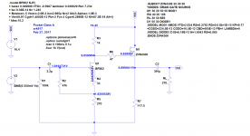
The Mofo needs over 15V peak, 30V peak-peak, drive to get all the power you paid for.
The plan you show has a 16V supply, so at a glance it can't make 30Vp-p. You probably need more like 32V-48V or +/-24V supply.
If it is inside the case, there is little need for the M1 buffer. (In fact conceptually the MoFo "is" the same function as the M1 buffer, just bigger and choke-loaded.)
Pass DIY Addict
Joined 2000
Paid Member
I'm obviously doing something wrong with my MoFo testing, but I am not quite sure what it is, so I'm hoping someone here can provide some insight for me.
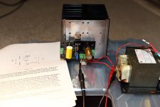
I am using the MoFo boards from the store, a 19.5v Dell laptop power supply, and a 5"x5"x5" sink that is sufficient for dissipating about 50w. The output inductor is a mains transformer from a microwave oven - I'm using the primary winding which measures about 0R54 DCR, ~58mH, and is wound with 15ga wire.
Starting up the amp, all goes as expected. Not much voltage across the inductor until I get a few turns on the pot. Voltage across the inductor comes up as I continue to turn the pot. I set the amp to about 2.5A bias (2.5A * 0R54 = 1.35v across inductor terminals) with a 19.5v power supply, so the mosfet is burning off about 48w.
The sink warms up slowly and after an hour measures about 47c (ambient is 21c). The highest temp I can find with the thermocouple probe on my DMM is about 55c on the mosfet mounting screw. Nothing is connected to the input or the output.
After powering down, the amp won't bias up again - the IRFP250 transistor is fried.
Is this just too much power/temperature for the mosfet? Why does it keep frying?
Attachments
- Home
- Amplifiers
- Pass Labs
- Build This MoFo!