Even cheaper option is the 159ZC, also open framed. I believe someone on this thread tried it at 2.5A (bias of big MoFo) with no ill effect.
That would be me. I use the 159ZC with a small IRFP250 and a big IXYS mosfet. I can switch between the two. The 250 is biased around 1.8A I think and the big IXYS around 2.3A.
It is currently very, very hot in Holland. I made this amp during winter in my basement. At that moment it was around 17°C (63F). It is now close to 30°C in my listening room (86F), so the amp is running a bit hot with the IXYS. Yesterday I switched the whole evening between the 2 Fets and biases and there is not a big difference. Maybe the IXYS with the higher bias has a bit fatter bass. Might be due to a little distortion. Don't know, don't care. I like the result.

One more thing: I read thinks about using huge inductors with low resistance. Why not go for a balanced version? Make 2 MoFo's per channel. Use 2 inductors with half the inductance (if I'm not mistaking). Lower the voltage and crank up the bias a bit. You could use the 159ZE with 3A and 15V. You would have a lot of power and you can even drop the output caps.
Problem can be driving this balanced version if you don't own a balanced pre amp. Finding a decent signal transformer for these high voltages is difficult.
Thanks Jostwid, I'll order the 195T then. Postage is free actually.
As for being open framed, it doesn't matter does it?
"Pottet or not pottet" was once an article in "Soundpractices" magazine. Actually open frame is preferred by many when speaking about electrical and sound properties. Aesthetics are another question.
As for myself i would, like others mentioned already, go for the cheap 159ZC. The only reason to go for the 195T5 is to go to high amperage maybe when using a big IXYS part
Simple SRPP tube amp. I use a 6N6P. Close to ECC99 or 12BH7. No issues. Nice open sound. No stresssssss.
Cheap to build (if you can get russian tubes directly from Russia or a former Sovjet countrey). I bought a box 6N6P from Moldavia and paid something like 40 dollars for a box of 20). All brand new Mil spec.
Cheap to build (if you can get russian tubes directly from Russia or a former Sovjet countrey
). I bought a box 6N6P from Moldavia and paid something like 40 dollars for a box of 20). All brand new Mil spec.I'm proposing to use the MoFo with my valve pre having Sowter 9525 inter stage transformers with the output floating and not tied to the 0V rail, Niobium - Valve pre for SS Power Amp - audio-talk
Will I be able to bypass C1 as per the attached? View attachment 18-07-20 MoFo Inter Stage Schematic.bmp
Will I be able to bypass C1 as per the attached? View attachment 18-07-20 MoFo Inter Stage Schematic.bmp
I'm proposing to use the MoFo with my valve pre having Sowter 9525 inter stage transformers with the output floating and not tied to the 0V rail, Niobium - Valve pre for SS Power Amp - audio-talk
Will I be able to bypass C1 as per the attached? View attachment 692751
It's hard to see on the schematic what you are intending . What you need to do is place the transformer secondary in series between the gate stopper and the bias circuitry of the the mosfet . I notice you have placed a load resistor on the IT secondary . Was this value derived according to the capacitance presented by the mosfet ?
316a
What you need to do is place the transformer secondary in series between the gate stopper and the bias circuitry of the the mosfet . I notice you have placed a load resistor on the IT secondary . Was this value derived according to the capacitance presented by the mosfet ?
316a
OK so if I wanted to have 2 inputs, I need to divert the bias voltage via the inter stage transformer with a switch. Potential scheme attached. Unsure whether the second set of switch contacts from inputs to the gate stopper is needed and seems like quite something just to get rid of C1. View attachment 18-07-20 MoFo Inter Stage Schematic.bmp
Perhaps just be easier investing in a better C1 if I'm that bothered about it's sonic impact.
Or probably easier, just lift one end of R2 and R3, and wire direct to an RCA input.
The load resistor on the transformer secondary is not specific to any particular valve or solid state output stage. Possibly does nothing in this particular config so could/should be removed.
Last edited:
OK so if I wanted to have 2 inputs, I need to divert the bias voltage via the inter stage transformer with a switch. Potential scheme attached. Unsure whether the second set of switch contacts from inputs to the gate stopper is needed and seems like quite something just to get rid of C1. View attachment 692780
Perhaps just be easier investing in a better C1 if I'm that bothered about it's sonic impact.
Or probably easier, just lift one end of R2 and R3, and wire direct to an RCA input.
The load resistor on the transformer secondary is not specific to any particular valve or solid state output stage. Possibly does nothing in this particular config so could/should be removed.
Looks like a complete mess , I just enlarged the schematic and it's not readable at all now . I don't understand what you are attempting to do . Surely , your input selector goes at the input of the linestage ?
316a
Surely , your input selector goes at the input of the linestage ?
316a
I wanted to keep the option of connecting an input via R1/C1, but also have a second rca input that I could wire from my valve pre output transformer, bypassing C1 and connecting direct to the gate stopper.
Going to just do the latter, lifting one end of R2 and R3 and wiring direct to an RCA socket.
Thanks for the advice.
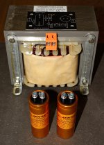
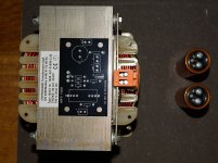
I picked up the big chokes for the MoFo project today. I already got the PCBs from the DIY store. The large Jensen capacitors is for the output capacitor. They have very low ESR and inductance and made for audio. Same type worked great with the ACA. The set of bias may be a challenge. When I measure the RDC my DMM just shows 0.1 Ohm so difficult to use that to measure a voltage when setting the bias other than an appox. value and so both channels will be identical. To make an exact measurement I need something in the circuit that will not change the value when removed. I may have to learn some tricks.
The choke is made with 12.5 mm2 flat copper wire. They said at the factory that round wire does not work when chokes gets that big. It can handle much more than 3A.....exactly how much before the iron is saturated I don't know. So far so good…...it will take a while before it is ready for the first test.
The choke is made with 12.5 mm2 flat copper wire. They said at the factory that round wire does not work when chokes gets that big. It can handle much more than 3A.....exactly how much before the iron is saturated I don't know. So far so good…...it will take a while before it is ready for the first test.
Attachments
Yes, it will be fun to see what challenges I will face...….
On pictures it looks much smaller than in real...…
The 3A DC written on top is just my original design requirements. It can handle much more as it was the requirement for low RDC that demanded the big size. Will see how it goes……..
On pictures it looks much smaller than in real...…
The 3A DC written on top is just my original design requirements. It can handle much more as it was the requirement for low RDC that demanded the big size. Will see how it goes……..
Attachments
Where did you source the Jensen 6800uF capacitors?
I'm going to build a second MoFo (probably with CPU coolers this time) and would be open to try those screw top caps.
The Jensen caps are 6800 uf / 63 VDC. Have four as I will use two pr. channel in parallel. I picked them up direct at the Jensen factory close to Copenhagen. I was served by the 3. generation of Jensen. They are two 3. generation Jensen brothers which own the factory now. These 6800 uF are not listed at the web. They are not cheap…...approx. 120 USD each incl. 25% Danish tax. I like to use the local suppliers. The chokes were also picked up at the factory.
These 6800 uF are not listed at the web. They are not cheap…...approx. 120 USD each incl. 25% Danish tax. I like to use the local suppliers. The chokes were also picked up at the factory.
That's why I couldn't find them anywhere, thanks MEPER.
If you have a dc supply you can push a known current thru and measure the voltage across the coil.I picked up the big chokes for the MoFo project today. I already got the PCBs from the DIY store. The large Jensen capacitors is for the output capacitor. They have very low ESR and inductance and made for audio. Same type worked great with the ACA. The set of bias may be a challenge. When I measure the RDC my DMM just shows 0.1 Ohm so difficult to use that to measure a voltage when setting the bias other than an appox. value and so both channels will be identical. To make an exact measurement I need something in the circuit that will not change the value when removed. I may have to learn some tricks.
The choke is made with 12.5 mm2 flat copper wire. They said at the factory that round wire does not work when chokes gets that big. It can handle much more than 3A.....exactly how much before the iron is saturated I don't know. So far so good…...it will take a while before it is ready for the first test.
That's why I couldn't find them anywhere, thanks MEPER.
At the Jensen web you can find them in 10.000 uF with a different form factor (larger diamenter and not as tall). I think the 6800 uF may be from a special production as they have just a label on and not printed as they do on their standard production.
When I measure their impedance they go to quite low ESR and they stay low up to very "high" frequencies. They have not the usually E-cap curve where the impedance goes up with raising frequency. At 100 kHz the impedance is almost same as the ESR (just raised a tiny bit). A normal 10 USD E-cap with same uF / VDC will not measure as good…..at least not the measurements I have performed (it is not that many…..but my experience so far).
- Home
- Amplifiers
- Pass Labs
- Build This MoFo!