Power on….jezz-O-Pete….that cooler works great.
Inductor measures .53ohm X 2.5 (bias) = 1.325v.
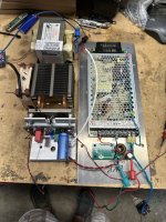
Was on for an hour. Bias, once set, barely went up. SMPS is maybe warm. Inductor is room temp.
I hooked up that mosfet & it was perfect! Unfortunately it was backwards. A bit of juggling was in order. On to assembly.
Inductor measures .53ohm X 2.5 (bias) = 1.325v.
Was on for an hour. Bias, once set, barely went up. SMPS is maybe warm. Inductor is room temp.
I hooked up that mosfet & it was perfect! Unfortunately it was backwards. A bit of juggling was in order. On to assembly.
Attachments
Pass DIY Addict
Joined 2000
Paid Member
Those CPU coolers work pretty well. I picked up one for a recent computer build that is rated to ditch about 100w of heat, so with a single mosfet, you're looking at less than half of that. One of the things I like about the MoFo buffer is that it seems to produce a bit more bass than other amps due to the huge coil.

Way back on post # 61 PRR mentioned choke size may not limit the low frequency
cuttoff frequency as much as it does the power bandwidth. Like our 50 mh choke
will have a inductive reactance of about 6.8 ohms at 30 hz so only about 50% of
the power output would be avaliable to the speaker. Keeping this in mind and the
comments that we might not need as much inductance if we didn't need the extended
base responce. I tried to figure what size inductor I would need to use this with a full
range driver crosed over at 500 hz. So it looks like building this with a 5mh inductor may
limit our power bandwidth below about 250 hz. But as I will be using an active xover and be
down about 18db by 250 hz I won't have to worry about that.
I already have a pair of 4.8 mh 12A chokes with a dcr of only .052 ohm. After
doing the calculations again 2A through that .052 ohms will give me only about
104 mv across that inductor. Well with only 104 mv across the inductor I bet I could
just do away with output cap.
Pass DIY Addict
Joined 2000
Paid Member
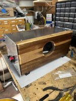
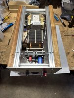
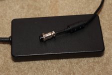
I just finished rebuilding my MoFo. I really liked the open "bread board" style of my first build (images here) but I wasn't crazy about having all of the signal and power connectors on the front of the amp. This made it a bit awkward to get the cables connected. While I was working on the redesign, I replaced the DC power entry that I wasn't really crazy about. The original DC in was a laptop power adapter plug that I had cut, but it really wasn't intended to handle the current that the MoFo draws and it got a little warm (but still safely under the typical 60c rating). This time around, I replaced it with an aviation-style plug that provides both a more secure connection and is rated to handle better the current draw.
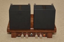
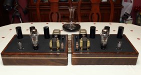
So, five years later, I rebuilt it in the same style and moved all of the connectors to the rear of the amp. This gives it a little bit of a cleaner presentation, yet retains the overall appearance that I like so much. In the end, it was a whole bunch of work to make a small alteration in its overall appearance. Should have planned better the first time around...
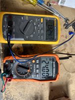
Overall bias is set to about 2.5A per channel on a 19.5v Dell power brick that is rated for 240w, so there is a good safety margin in place.
So, five years later, I rebuilt it in the same style and moved all of the connectors to the rear of the amp. This gives it a little bit of a cleaner presentation, yet retains the overall appearance that I like so much. In the end, it was a whole bunch of work to make a small alteration in its overall appearance. Should have planned better the first time around...
Overall bias is set to about 2.5A per channel on a 19.5v Dell power brick that is rated for 240w, so there is a good safety margin in place.
Attachments

Pass DIY Addict
Joined 2000
Paid Member
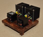
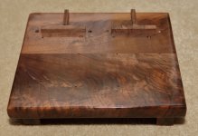
Thanks, guys! I've had that slab of Walnut laying around for a while, picked it up because I liked the striping in the grain. It was originally a 5.5"w by 30" long plank that I cut and glued together to make it roughly square. I did a little work to clean up the MOT before painting them. I removed the leads for the unused coil and cut back some of the resin-infused paper shrouding. Then I taped over the exposed winding to keep it copper color. It turned out better than I thought it would.
The laptop brick is rated for 19.5v at about 12A (240w total) and each channel draws about 48w (2.5A bias). Voltage sags to 19.1 for both channels, and overall its a 100w draw from a brick rated for 240w. It gets to just a bit over body temp, but I haven't made an actual measurement because it's just not a concern. I've run each channel at 3A bias for a few months without issue, but backed it down for longevity of the mosfet (3A = 60w). The mosfets are mounted directly to the sink with just a bit of thermal goop, there is no electric insulator, so the sinks are live at 19v.
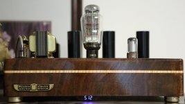
One of these days, I might put the MoFo between my 300B amps and my big Calpamos speakers. The impedance curve of the Calpamos isn't quite 7w tube friendly. The digital volt meter helps me keep the 300B filament in the 5v0 to 5v2 range that Jac recommends for the meshplate tube. I have an outboard box for it with two different bucking transformers that I switch in and out depending on the AC voltage level for the day.
The laptop brick is rated for 19.5v at about 12A (240w total) and each channel draws about 48w (2.5A bias). Voltage sags to 19.1 for both channels, and overall its a 100w draw from a brick rated for 240w. It gets to just a bit over body temp, but I haven't made an actual measurement because it's just not a concern. I've run each channel at 3A bias for a few months without issue, but backed it down for longevity of the mosfet (3A = 60w). The mosfets are mounted directly to the sink with just a bit of thermal goop, there is no electric insulator, so the sinks are live at 19v.
One of these days, I might put the MoFo between my 300B amps and my big Calpamos speakers. The impedance curve of the Calpamos isn't quite 7w tube friendly. The digital volt meter helps me keep the 300B filament in the 5v0 to 5v2 range that Jac recommends for the meshplate tube. I have an outboard box for it with two different bucking transformers that I switch in and out depending on the AC voltage level for the day.
Attachments
Last edited:
Pass DIY Addict
Joined 2000
Paid Member
Oh, jeez, that image is a few years old. Impossible to tell who's red is in the decanter ") . I do enjoy Mondavi products, though. I'm not fond of white wines at all, so the entire cabinet is full of reds...
. I do enjoy Mondavi products, though. I'm not fond of white wines at all, so the entire cabinet is full of reds...
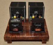
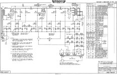
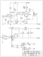
The output transformer is a little on the small side, clearly not 3-4 kg. This is also because it's a parafeed design, so it doesn't carry the B+ and doesn't need the same mass as a more "traditional" 300B output transformer. The chassis itself is also large (I used lots of "period" Russian military PIO caps in the design), so everything looks a little smaller in comparison. The wooden chassis front panel is 4" tall and 18" wide and the 300B is an EML Meshplate that is nearly 7" tall, which is bigger than most. The circuit has an interesting history. The original is the Western Electric 91A from 1936 or so (attached). In 1992, Joe Roberts published an update to this design in Sound Practices (also attached). In 2013, Paul Joppa (of Bottlehead) updated Joe's design using Magnequest iron (also attached). This is what I've built, with a few minor tweaks. It's quite a nice sounding amp.
. I do enjoy Mondavi products, though. I'm not fond of white wines at all, so the entire cabinet is full of reds...The output transformer is a little on the small side, clearly not 3-4 kg. This is also because it's a parafeed design, so it doesn't carry the B+ and doesn't need the same mass as a more "traditional" 300B output transformer. The chassis itself is also large (I used lots of "period" Russian military PIO caps in the design), so everything looks a little smaller in comparison. The wooden chassis front panel is 4" tall and 18" wide and the 300B is an EML Meshplate that is nearly 7" tall, which is bigger than most. The circuit has an interesting history. The original is the Western Electric 91A from 1936 or so (attached). In 1992, Joe Roberts published an update to this design in Sound Practices (also attached). In 2013, Paul Joppa (of Bottlehead) updated Joe's design using Magnequest iron (also attached). This is what I've built, with a few minor tweaks. It's quite a nice sounding amp.
Attachments
Since this is a relatively straightforward design I thought I would try wiring point to point on a board. The first channel went as planned and biased up fine. The second one however, gave up magic smoke from the 6800uF cap. I briefly checked the voltage into the board with my multimeter accidentally set to AC instead of DC. Would this cause such a catastrophe?

Regards,
Rogster
Regards,
Rogster
- Home
- Amplifiers
- Pass Labs
- Build This MoFo!