the rubycon on vfet kit is quite goodI didn't mean esoteric. I usually pick whats most available on Mouser, no brand preference. Mainly concerned with the uF. I've seen input caps from 1uF to 10uF, and on the output 2200uF-10000uF, sometimes with a film and not. I know it has to do with obtaining a certain frequency response, but with a bigger device, does it really matter?
This is for entertainment.
So, if one enjoys trying different output coupling caps, or especially combinations of coupling caps in parallel, it’s all good.
I have also been happy with the Rubycon cap as used by the latest VFET amps from Papa. Even more so when adding a Nichicon KW series 470uF cap in parallel.")
So, if one enjoys trying different output coupling caps, or especially combinations of coupling caps in parallel, it’s all good.
I have also been happy with the Rubycon cap as used by the latest VFET amps from Papa. Even more so when adding a Nichicon KW series 470uF cap in parallel.
The coupling cap and speaker form a 1st order low pass filter. To calculate how big of a cap you need use the formula for the -3dB corner frequency: F3 = 1/(2 pi x R x C). Let’s assume you want your amp to be “flat” down to 10Hz. If we set the F3 corner frequency 2 octaves lower it should be pretty flat at 10Hz. 2 octaves lower is 2.5Hz. Assume you have 8 ohm speakers. Solve the equation for C and we get C = 1/(2pi x R x F3) = 1/(6.28 x 8ohm x 2.5Hz) = 0.008F or 8,000uF. That’s pretty close to 6800uF.
You could calculate F3 with 6800uF and we get F3 of 3Hz. 2 octaves higher is 12Hz.
Note that lower impedance speakers require larger caps to reach the same bass response.
You could calculate F3 with 6800uF and we get F3 of 3Hz. 2 octaves higher is 12Hz.
Note that lower impedance speakers require larger caps to reach the same bass response.
the rubycon on vfet kit is quite good
Rubycon was the mfg of the now out of production Black Gate caps

Happy birthday Mike, hope you are all well.
Happy birthday to the Dude as well (brilliant write up)
Have you spoken anymore to the Dude about the update to the MoFo or is he too busy bowling?
Living in Spain I have been looking for a summer amp. This one seems to fit the bill with 19V and 1.7A. Should I wait for the Dude or just build as is (no pressure please)

 , it's just variations on a theme and you'll be able to re-use the iron bits.
Adjusting resistor values for use with 1:3 SUT at input?
Hi all - hoping someone can help with a couple of noob questions. I've read through about the first half of this thread and haven't seen answers - but apologies if they've been answered elsewhere.
I have a couple of nice tube preamps that (a) don't swing quite as much voltage as I'd like for the MOFO, and (b) have output impedances of approx. 600R and 2000-ish R respectively.
So I'd like to experiment with using a 1:3 SUT at the input to get 3X signal voltage gain, but as I understand things, this will come at the price of 9X reduction of the load impedance that the preamp sees.
Can I avoid this by increasing the values of P1, R1, R3 and R4 by a factor of 10 as shown in the attached? Are there any problems, sonically or otherwise, with doing this?
And if I can do this, am I correct that I can then reduce the size of C1 by a factor of 10, without changing the -3 dB cut-off frequency (f = 1/(6.28*C*R))?
cheers and many thanks in advance, Derek
Attachments
Hi all - hoping someone can help with a couple of noob questions. I've read through about the first half of this thread and haven't seen answers - but apologies if they've been answered elsewhere.
I have a couple of nice tube preamps that (a) don't swing quite as much voltage as I'd like for the MOFO, and (b) have output impedances of approx. 600R and 2000-ish R respectively.
So I'd like to experiment with using a 1:3 SUT at the input to get 3X signal voltage gain, but as I understand things, this will come at the price of 9X reduction of the load impedance that the preamp sees.
Can I avoid this by increasing the values of P1, R1, R3 and R4 by a factor of 10 as shown in the attached? Are there any problems, sonically or otherwise, with doing this?
And if I can do this, am I correct that I can then reduce the size of C1 by a factor of 10, without changing the -3 dB cut-off frequency (f = 1/(6.28*C*R))?
cheers and many thanks in advance, Derek
I can't comment on your schematic, but this topic has been discussed before as I was in a similar situation as you. An alternative would be to place a JFET Buffer before the step-up transformer, the B1 buffer might work. Then just leave the MoFo circuit alone. You'd basically be building a single ended version of the M2 I suppose. Unfortunately, I never got around to building this scheme, but it's worth thinking about. Michael Rothacher's "Fe1" circuit described in the BAF 2021 video could be another solution. Just a JFET voltage gain front end providing enough swing to drive the MoFo directly. Relatively low 10K input impedance though.
Would be ideal to drive the SUT directly from the preamp, but there's always a compromise somewhere...
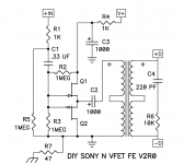
thake a look at vfet kit, Pa is a geniusI can't comment on your schematic, but this topic has been discussed before as I was in a similar situation as you. An alternative would be to place a JFET Buffer before the step-up transformer, the B1 buffer might work.
Attachments
I can't comment on your schematic, but this topic has been discussed before as I was in a similar situation as you. An alternative would be to place a JFET Buffer before the step-up transformer, the B1 buffer might work. ... Michael Rothacher's "Fe1" circuit described in the BAF 2021 video could be another solution. Just a JFET voltage gain front end providing enough swing to drive the MoFo directly. ...
Many thanks for responding Jenghis. In my reading late last night I finally reached the point in this thread where you and others discussed this. Yeah, a buffer with a high-ish (or at least high-er) input impedance and low output impedance in front of the SUT might be the way to go. I'll also check out the Fe1. Thanks for pointing me in the direction of that.
But first, I'll try my 10X resistance idea - just to see. Resistors are cheap and I'll be building the MoFo on plain FR4 board, which was also cheap - so no big deal if the experiment doesn't work out. I have two pairs of trafos on hand that will be fun to experiment with: tiny Hammond 124B and huge, zero-gapped LL2765 Lundahls - both of which will give me the 1:3 step up I'm looking for. If the experiment works, I'll consider shelling out for some nice supermalloy or amorphous core SUTs designed or spec'ed to work well for my situation.
I am brand new to solid state amplification (and still pretty new to tube amps, too). But having watched a few "how mosfets work" videos
, I *think* the 10X resistor value approach might work. As best as I can tell, P1 and R4 form a voltage divider for setting the bias voltage at the gate. Meanwhile, R1 in parallel with series P1(lower leg)-R3 form the load that the previous stage sees. If so, then my guess is that I can increase all of these resistors by a factor of 10 to get the 10X bigger input impedance that I want for the SUT without changing the voltage divider ratio for setting bias. Time will tell ... maybe it will work, maybe not. 
thake a look at vfet kit, Pa is a genius
Many thanks Nicoch58. I will also check this out -- although I suspect that this is specific to the now unobtainium Sony Vfets?
If anyone has any thoughts/speculations about my 10X resistance idea, I'd love to read them.
cheers, Derek
Last edited:
Transformers are tricky Blighters into any capacitance.
Buffer to step up transformer? Surely Step up then buffer? to buffer the input
Transformer ringing with the Mofo input capacitance. I know this is Bootsrapped and approx a factor of 10 ish smaller than the raw Mosfet(or whatever) but after spending time with my carefully snubbed input transformers(various sowters and lundahls of variouse flavours 600/600, High impedence, Line level output) a signal source and oscilloscope, Mofo input makes them all ring in reality. It took me approx 22k or more of Mofo series input resistance to make this totally go away.
Mofo makes the best sounding headphone amplifier EVER, but with this much series input resistance unfortunately my Mofos had a just audible hum through sensitive headphones. Maybe just my set up but I feel this is an inelegant sollution.
Just my personal possibly incompetent experience.
As an aside could you have a line level Fet MOFO (Low capacitance) as the input Buffer? so as to use the same power supply and still have the choke doubled (ish) voltage headroom?
- Home
- Amplifiers
- Pass Labs
- Build This MoFo!