@ranshdow - I thought the intention with the MOTs was to use the primary winding not the secondary
I always used the primary. Not sure where you are seeing the secondary? The wire I'm using to hook the MOTs up is salvaged, and is hooked into the lower primaries. It may be the same type of wire as the filament secondary which I clipped off on some of the MOTs.
Last edited:
") , you had me fooled
, you had me fooled 
I've read the 300 pages and made notes so I think I am ready to to build a Big Mofo now! That a great dream story MR.
I have built Nelson Pass Aleph J and wanted to compare it against the Big Mofo.
I want to focus on making the set as small as possible, mainly using a single 10A 24 volt power supply and using computer heatsink/fan combination. 1 per FET.
I have Paradigm S2 Signature Reference speakers which state Sensitivity: 88dB/2.83V/m Impedance: "compatible with 8 ohms." or combined resistance of 5.2 ohm?
Attaching the plots I see that 3.6 ohms is the lowest resistance seen at 180hz F#3/Gb3
What changes or considerations do I need for my speakers? DO I just treat them as 8 ohm speakers?
My final question is will 10A 24v power supply adequate for both channels?
I don't needs gobs of power but since I already have the power supply I figured I would use it. Someone mentioned that if I turn my PSU down to the minimum (22.5 vDC) and use a CapMx I can consider the 19V version?
Any insight or suggestions are appreciated.
Attachments
Pass DIY Addict
Joined 2000
Paid Member
Those look like 4 ohm speakers to me. To get better power delivery out of the amp into a 4R load, just push the bias a little higher, if you find it necessary.
Your 10A PSU will be fine for one or both channels.
Edit: See this link for some details: Bias Levels, PSU Voltage, and Speaker Impedance from PRR:
Your 10A PSU will be fine for one or both channels.
Edit: See this link for some details: Bias Levels, PSU Voltage, and Speaker Impedance from PRR:
Last edited:
I have built Nelson Pass Aleph J and wanted to compare it against the Big Mofo.
[...]
Any insight or suggestions are appreciated.
If you're hoping the MoFo will sound better than the Aleph J, you may be disappointed. I've borrowed a friend's Aleph J and played it in a system where I was using an ACA in stereo mode for a long time and the Aleph J sounds like the ACA's big brother- better diction and control, more forceful sound, but with similar overall coloring. I used that same ACA (now in bridged mono mode) as a comparator to one of my MoFo channels on more sensitive speakers and the ACA was noticeably better. So by inference Aleph J > ACA >> MoFo. YMMV.
@ranshdow - Interesting. Was the B1K the only preamp you used with Mofo? I've been interested in the M2X. Now I'm wondering if I should just go for an M2X rather than building more preamps for the Mofo
I'm currently in the garage listening to dual mono MoFos using a passive preamp design by Jack Eliano of Electra-Print, fed by a RPi with a DAC HAT, and feeding a pair of Klipsch RP-150M's. The passive pre offers ~8:1 voltage gain using Jack's PVA-2n line-level trafos. It might be my imagination but the system sounds better the longer it's playing? I have no idea what voltage swing the MoFos are getting. The MOSFET of one MoFo is getting up to 69C like before.
Also, keep in mind I'm using lower voltage bricks (~19.5V) and IRFP240's, not the higher power IRFP250's that Michael originally spec'd. The R(ds-on) of the Vishay 240's is 0.18R vs. 0.085R for the 250's, all else being equal the 250's will draw and handle more current. I'm tempted to try my bench supply with one channel to goose the voltage but I'm worried about frying the MOSFET.
Last edited:
It’s very doubtful you’ll fry the mosfet. Yes, they run hot. Wether or not it works well at higher voltage is mainly predicated on the choke not saturating at the bias you run it.
Great description of ACA vs. Aleph sound.
MoFo doesn’t really fall into the same category, in my opinion, much like F4, as it’s a follower, and is very dependent sonically on the preamp providing the voltage gain.
Great description of ACA vs. Aleph sound.
MoFo doesn’t really fall into the same category, in my opinion, much like F4, as it’s a follower, and is very dependent sonically on the preamp providing the voltage gain.
Thanks for the advice re the MOSFET. For a noob, these temps seem high despite the big heatsinks. It would be good if I learned how to properly measure the DC saturation characteristics of these chokes and MOTs I seem to be collecting.
I would like a third preamp, one that could swing high voltages, as I expect I'll be playing with other common-drain amp topologies once I decide what to do with my SITs.
I would like a third preamp, one that could swing high voltages, as I expect I'll be playing with other common-drain amp topologies once I decide what to do with my SITs.
@rannshdow, AKSA'S Lender Pre-amp was designed to provide high voltage swings.
AKSA's Lender Preamp with 40Vpp Output
Kind regards,
Drew
AKSA's Lender Preamp with 40Vpp Output
Kind regards,
Drew
Gosh, the more I listen to these MoFos in the garage the more I want to try them on my main system, little chokes and 19V bricks and all. I'd have to get rid of the alligator clips on input and output though, proper RCAs and speaker binding posts instead. They really need a good 45+ minutes to warm up & get into their groove.
Also 6L6, you're right the preamp seems to matter, and with the passive trafo pre I favor even the source seems to matter. One RPi with a high output Z seems to fall down a bit with the MoFos.
Also 6L6, you're right the preamp seems to matter, and with the passive trafo pre I favor even the source seems to matter. One RPi with a high output Z seems to fall down a bit with the MoFos.
Last edited:
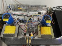
My Big MoFo ProTo-Type
Built a while ago, it has probably 100 hours on it. Next step is to put it in a proper enclosure. Parts are what I mostly had on hand.
I'm driving it with a Aikido pre-amp I've had for a long time. Speakers are Klipsch bookshelf models. It's a keeper.
Built a while ago, it has probably 100 hours on it. Next step is to put it in a proper enclosure. Parts are what I mostly had on hand.
I'm driving it with a Aikido pre-amp I've had for a long time. Speakers are Klipsch bookshelf models. It's a keeper.
Attachments
I've noticed that the current across the chokes creeps up as the MoFo's heat sink gets hotter. This is counter intuitive to me as there's a plot of R(ds-on) vs. temperature for the Vishay IRFP240's and the slope is positive, so the drain to source resistance of the device should be going up as it heats up. Is the resistance of the choke getting lower? In fairness it does seem to plateau after an hour or so, but I'm curious what drives the plateau point, as I don't want these things running away from me if they're unattended.
When I turn them on the chokes are dropping about 0.97V and an hour later when I can no longer touch the sinks for more than a split second (call it 60C), they're pushing 1.04V. With my measured choke DCR of 0.6R, the current is going from ~1.6A to ~1.73A. I don't trust my DMM at this level, and these chokes are spec'd as 0.3R, so the current might actually be more like 3.2 to 3.46A. The bricks are rated to deliver 4.7A so this is possible.
The heatsinks, which are rated at 0.41degC/W, are getting too hot to touch so let's call that 60C, or ~40C above ambient. I don't think these things are burning 97W though, the heatsinks aren't properly ventilated sitting on my bench. I'm measuring a drain to source drop of 18.5V under these conditions, so the MOSFETS are burning somewhere between 32W to 64W, depending on which DCR you believe. Yes I know I should get a half-ohm power resistor and put it in series with the chokes to measure the current exactly, but I wanted to see how far I could get with things as they are. Thoughts? I tried dialing down the bias when they were hot before but it seems like a moving target.
Pass DIY Addict
Joined 2000
Paid Member
I might be wrong, but I've understood that as chokes heat up, their resistance increases. This will likely drop more voltage, as you've noted. This might have the tendency to cause bias current to increase. 60c is getting pretty toasty.
In my MoFo amp, I have one sink for each channel and they are physically isolated from one another. Because of this, I mounted the mosfet directly to the sink using only some thermal paste and ran each channel at 60w dissipation. This makes things toasty, but still within my comfort zone. Images are in my signature link.
In my MoFo amp, I have one sink for each channel and they are physically isolated from one another. Because of this, I mounted the mosfet directly to the sink using only some thermal paste and ran each channel at 60w dissipation. This makes things toasty, but still within my comfort zone. Images are in my signature link.
I might be wrong, but I've understood that as chokes heat up, their resistance increases. This will likely drop more voltage, as you've noted. This might have the tendency to cause bias current to increase. 60c is getting pretty toasty.
Hm! If that's the case then the current draw shouldn't be going up as the chokes heat, it just looks like it does from the pt of view of the increasing voltage drop across them?
Can I replace the C1 value? I have couple of 1.5uF and 10uF caps. Others will be around 0.1uF or below. Changing the value does it changing the sound? What's the different using original value 2.2uF and 10uF or 1.5uF.
I want to build a linear power supply. What is the minimum transformer wattage and capacitance value? I have ordered a choke 65mH 5A/0.414ohm.
I want to build a linear power supply. What is the minimum transformer wattage and capacitance value? I have ordered a choke 65mH 5A/0.414ohm.
All the popular metals have positive coefficient of resistance vs temperature.
We know this from PA speakers. After a loud set at 100 Watts average the voice coil resistance may double.
And of course it has been known far longer in precision measurement. Low-tempco alloys for wirewound resistors are a hundred years old.
Constantan - Wikipedia 1887
If your chokes get more than slightly warm, you can't read current better than a few percent. I believe most standard resistors are better, or can be cheaply OVER-sized to stay cool, so a 0.1 or 0.05Ω in series may be useful.
- Home
- Amplifiers
- Pass Labs
- Build This MoFo!