Thank you for the measurements. Impressive what a well done Mofo does.
Exact! for many years I have underestimated this circuit because I thought it needed a layered / sectioned choke like the one used as anode load of the valves instead it was enough to take a simple inductance built for the power supplies this because the mosfet outptu impeance is very low.
.
Good work on presenting data for different Mosfets. I guess you plan to show data for different chokes as well?
I have a pair of FQH44N10 Mosfets that I plan to try in my MoFo after I solve my power supply issue. I was also looking at the IXTH64N10L2 for its ability to take a higher bias. It would be interesting to see simulated data for these devices.
What are you using for your power supply?
I have a pair of FQH44N10 Mosfets that I plan to try in my MoFo after I solve my power supply issue. I was also looking at the IXTH64N10L2 for its ability to take a higher bias. It would be interesting to see simulated data for these devices.
What are you using for your power supply?
What are you using for your power supply?
At this time I am using a 20VAC transformer, a MBR40250 diode bridge, 4700uF + 10mH 159ZJ Hammond + 4700uF.
Probably I will increase the value to 10000uF to support 5A.
Attachments
Thanks, that's good to know. I agree, the 10000 uF caps will probably be better at the higher bias. Perhaps two of the 10000 uF caps after the 159ZJ will be better still. Five amps is a lot of current, and will increase the power supply ripple significantly.
I tried using a 150W, 27V SMPS and ran into problems, as I mentioned earlier. I have a pair of 200W, 24V SMPS on their way. I am also going to try a CFP-based CapMx with the units I have to smooth the ripple and augment the current delivery when the amp is playing a signal. I also have plans to build a MrEvil style CapMx regulator for the new SMPS when they get here.
I tried using a 150W, 27V SMPS and ran into problems, as I mentioned earlier. I have a pair of 200W, 24V SMPS on their way. I am also going to try a CFP-based CapMx with the units I have to smooth the ripple and augment the current delivery when the amp is playing a signal. I also have plans to build a MrEvil style CapMx regulator for the new SMPS when they get here.
I am still uncertain about the final output power because surely exceeding 90W of dissipation leads us to use 2 mosfets in parallel because I believe that a single mosfet cannot transfer heat well to a 300mm wide heatsink that I intend to use.
I would like to be sure that using 2 mosfet in parallel we have the same distortion level of one in the same condition.
I would like to be sure that using 2 mosfet in parallel we have the same distortion level of one in the same condition.
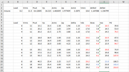
First test on different mosfet, the distortion is only on the 6072A driver stage if the drain voltage is enough and the source current is enough.
IRFP150 1.5euro 160W 1900pF
=> 26VDC 3.6A Vg=6.4V Vl=2.3V 1.8% thd 16Vrms load 8ohm 30W
SCT3030ALGC11 22 euro 260W 1500pF
=> 26VDC 3.6A Vg=8.2V Vl=2.3V 1.8% thd 16Vrms load 8ohm 30W
SCT3040KLGC11 30 euro 260W 1337pF
=> 26VDC 3.6A Vg=8.0V Vl=2.3V 1.8% thd 16Vrms load 8ohm 30W
IRFP150 1.5euro 160W 1900pF
=> 26VDC 3.6A Vg=6.4V Vl=2.3V 1.8% thd 16Vrms load 8ohm 30W
SCT3030ALGC11 22 euro 260W 1500pF
=> 26VDC 3.6A Vg=8.2V Vl=2.3V 1.8% thd 16Vrms load 8ohm 30W
SCT3040KLGC11 30 euro 260W 1337pF
=> 26VDC 3.6A Vg=8.0V Vl=2.3V 1.8% thd 16Vrms load 8ohm 30W
Hi,First test on different mosfet, the distortion is only on the 6072A driver stage if the drain voltage is enough and the source current is enough.
IRFP150 1.5euro 160W 1900pF
=> 26VDC 3.6A Vg=6.4V Vl=2.3V 1.8% thd 16Vrms load 8ohm 30W
SCT3030ALGC11 22 euro 260W 1500pF
=> 26VDC 3.6A Vg=8.2V Vl=2.3V 1.8% thd 16Vrms load 8ohm 30W
SCT3040KLGC11 30 euro 260W 1337pF
=> 26VDC 3.6A Vg=8.0V Vl=2.3V 1.8% thd 16Vrms load 8ohm 30W
I wonder about the difference between a vertical and a lateral especially designed for audio. Btw I had very good results with four 2SJ162 wired parallel and polarity reversed also.
Your comments ?
Regards
Mehmet
First test on different mosfet, the distortion is only on the 6072A driver stage if the drain voltage is enough and the source current is enough.
IRFP150 1.5euro 160W 1900pF
The SCTs remind me of the Semisouth 120R100. This proofed to be of big advantage in the second version of the Firstwatt F2. But in follower mode there is apparently no advantage
Hi,
I wonder about the difference between a vertical and a lateral especially designed for audio. Btw I had very good results with four 2SJ162 wired parallel and polarity reversed also.
Your comments ?
Regards
Mehmet
2SJ162 P channel used in this project ?
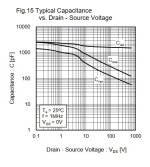
I would like to test the IXFN50N120SK with SOT-227 package and low input capacity 1850pF
Last edited:
The low capacity is at Vds of 1000V. I wonder how much it is at Vds 20V?
Yes, the capacity will be higher at 20-30V but if this follow this trend should not be a problem (here the plot of another model).
Attachments
Overload when loudspeaker are disconnected?
I am building a pair of big MoFo. It sounds and measures great, but it happened that I had some signal @input while there was a missing load on the output and current absorbed rised over 10 amps. Is it normal? What should I do to avoid this behavior that may occur for a mistake?
I am building a pair of big MoFo. It sounds and measures great, but it happened that I had some signal @input while there was a missing load on the output and current absorbed rised over 10 amps. Is it normal? What should I do to avoid this behavior that may occur for a mistake?
GS zenner in place?
Ops.... no! 😑 Should I place a 10 volt zener between Gate and Source to avoid this behavior?
certainly
Great! I felt I was missing something 😅
Does this zener effect audio performance? Just curious...
Hi,2SJ162 P channel used in this project ?
I would like to test the IXFN50N120SK with SOT-227 package and low input capacity 1850pF
Yes, first tried IRFP150, then lateral P channels.
It sounds amazing with lower bias for each.
Total bias is around 4 amps. Sth odd ?
I think laterals are more linear.
Regards
Mehmet
GS zenner in place?
Excuse me, for the big MoFo (24V 2.5A bias) should I use a 5W 20V gate-source zener as stated in the schematic you posted some time ago or should I use some different value?
Thanks in advance 😊
- Home
- Amplifiers
- Pass Labs
- Build This MoFo!