Is this the modification you are thinking about performing?
_
I got the sense that he wanted caps at each input ground lug to chassis ground.
thanks for the great suggestions, guys! A few questions/comments:
2. I don’t recall anything in the kit or instructions about a small ceramic capacitor between shield lug of capacitor and chassis. If I should have that, can somebody provide more details? I don’t know what “small ceramic” means.
I'm thinking he meant shield lug of the input socket, not capacitor. Small ceramic caps are used to block or redirect high frequencies especially radio frequencies.
Is this the modification you are thinking about performing?
_
Well, that's interesting. Is this something you've done and liked?
I'm thinking he meant shield lug of the input socket, not capacitor. Small ceramic caps are used to block or redirect high frequencies especially radio frequencies.
You are correct; I meant between the shield lug of both the input and output RCA sockets and chassis.
If you look in many schematics, you will see that some mfg. include the ceramic bypass capacitor. to chassis. A ceramic capacitor is needed because it operates at RF frequencies (do not use a film capacitor for an RFI bypass to chassis). Values range from .001 to .1 uf, depending upon how low the RFI needs to be shunted to chassis. NOTE: I'm fairly sure the best implementation of this approach must also have the chassis being connected to house ground via the third pin in the house plug. That will drain off the RFI energy to earth for those situations where the transmitting equipment also relies on earth.
As far as to whether any or all of the measures I suggested are needed in any given user's situation, that is user specific. I have read as well as know many people who live near TV, radio, cell phone and other antennas who have problems with the RFI in their area. Remember the log law of irradiated energy.
Professional, high end audio and conscientious mfg may use one or more techniques to preclude RFI and EMF issues to ensure usability in a wide range of situations, some of which are rarely experienced by all but the most unlucky user. Nonetheless, they provide such over engineering because they feel it adds value in the minds of their users or to avoid time-consuming troubleshooting and bad word of mouth.
As this is DIY, feel free to take whatever approach you want: add nothing unless you experience a problem, or use the belt and suspenders if you are likely to experience a number of different and unpredictable situations or if the thought of downtime is not acceptable.
Is this the modification you are thinking about performing?
_
No it should be before the potentiometer to avoid a variable filter (volume potentiometer) and to catch HF/RF at the entrance. This standard RC filter solves/prevents many issues without any sonic penalty. In todays RF ridden environments this counts for many wideband preamp/buffer circuits including tube devices. Wooden or plastic casings are really best avoided for this reason.
Also the ceramic cap from the GND lug to casing can help just as other RF tricks. As almost anyone has a smart phone, LED lighting, wireless internet, bluetooth etc. one should not be surprised to pick up RF via RCA cables, speaker cables etc.
IMHO input filtering and muting (by shorting outputs to GND) should be done in quality designs as they only prevent nasties without penalties. Certainly when devices are produced for starting and unexperienced DIYers.
Last edited:
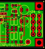
This recent discussion highlights the fact that the Korg kit leaves some questions to the builder to solve -- how to ground things properly is one, and another is dealing with power distribution when additions make simple one-to-one connections impractical.
I'm trying to fix that and provide other capabilities that I want in my preamp by adding an additional circuit card. The power supply end of the card allows the connection of multiple power connections, and for me, one of those connections is going to be a ground wire which will tie power ground to the chassis at or near the 24v input jack. My pcb standoffs don't connect the chassis to GND because they are rubber to help avoid microphonics.
It's going to involve moving the Korg pcb one inch toward the front panel and maybe up to an inch away from the power supply side, but the AA volume control leaves plenty of room for that, and this should resolve my wishlist.
Attachments
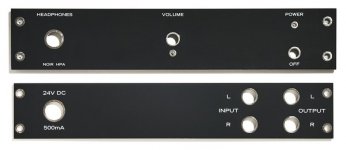
I've had good success using double sided, black PCBs for the front and rear panels, on line level equipment. The PCB fab does an excellent job of drilling and silkscreening the boards, which saves me time and aggravation in the workshop. Two copper layers provide excellent shielding and, thanks to plated-thru-holes, good electrical contact to the chassis mounting bolts. I also arrange the PCB to ground the body of the volume control potentiometer, which eliminates one common type of hum when using ALPS Blue Velvet pots. You can see the HASL plated copper hole beneath the volume control shaft -- that's where the pot body's alignment peg fits.
_
_
Attachments
I've had good success using double sided, black PCBs for the front and rear panels, on line level equipment. The PCB fab does an excellent job of drilling and silkscreening the boards, which saves me time and aggravation in the workshop. Two copper layers provide excellent shielding and, thanks to plated-thru-holes, good electrical contact to the chassis mounting bolts. I also arrange the PCB to ground the body of the volume control potentiometer, which eliminates one common type of hum when using ALPS Blue Velvet pots. You can see the HASL plated copper hole beneath the volume control shaft -- that's where the pot body's alignment peg fits.
_
That is a really good idea! printing front and back is always a hassle. Do you put a hard finish on them to avoid scratches?
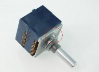
NuTube with power switch
Added on/off switch to extend the NuTube’s life. Ø=10mm hole. eBay sourced switch with built-in blue LED.
Tried to do the lettering of the front with water slide decals. Not the greatest of my attempts.
Added on/off switch to extend the NuTube’s life. Ø=10mm hole. eBay sourced switch with built-in blue LED.
Tried to do the lettering of the front with water slide decals. Not the greatest of my attempts.
Attachments
I've had good success using double sided, black PCBs for the front and rear panels, on line level equipment. The PCB fab does an excellent job of drilling and silkscreening the boards, which saves me time and aggravation in the workshop. Two copper layers provide excellent shielding and, thanks to plated-thru-holes, good electrical contact to the chassis mounting bolts. I also arrange the PCB to ground the body of the volume control potentiometer, which eliminates one common type of hum when using ALPS Blue Velvet pots. You can see the HASL plated copper hole beneath the volume control shaft -- that's where the pot body's alignment peg fits.
_
Where do you buy the black PCBs?
Black PCBs are an option that you can select, on the wonderful website
www dot pcbshopper dot com
Just now I did this, and received price quotes from seventeen different PCB fabs, to build qty=10 of 2-layer black PCBs. The cheapest price quote came from the fab named JLCPCB, and the most expensive was from Bay Area Circuits.
BTW the photos I showed in this thread, of black front panel and black rear panel PCBs, are actually a product which is sold by the diyAudio Store. Have a look at the photos attached to its sales page. Scroll down just a little bit to see thumbnail images of the available photos, then click on whichever ones you want to see full size.
Also, and this is probably a difficult question, but what would it be to convert one input of a B1 Korg Nutube to handle phono-level (for a moving magnet cartridge) input levels? From the spec sheet of my phono stage, I'm thinking this requires handling input in the range of 5-7.5mV, with an input loading of 47k and 100pF.
So is there a typical cycle to the kits coming back in stock? Seems like I've been waiting for 4-5 months now. Just curious if any posters have inside info.
Everything is usually available except for the small parts, and the lack of the small parts package seems to keep the full kit from being available.
With a full BOM figured out you could assemble the parts from the diyaudiostore, Digi-key, and Amazon. The only other part I had to source was a volume knob that fit inside the cutout on the front panel, which came from eBay/China.
Last edited:
Also, and this is probably a difficult question, but what would it be to convert one input of a B1 Korg Nutube to handle phono-level (for a moving magnet cartridge) input levels? From the spec sheet of my phono stage, I'm thinking this requires handling input in the range of 5-7.5mV, with an input loading of 47k and 100pF.
You will need a sensitive amplifier with the RIAA correction, e.g. a Threshold NS-10 circuit. But I do not know if your SMPS external AC/DC is silent enough.
You will need a sensitive amplifier with the RIAA correction, e.g. a Threshold NS-10 circuit. But I do not know if your SMPS external AC/DC is silent enough.
Yeah, I was aware that a proper phono stage implements the RIAA de-emphasis curve, but I kinda figured there were such implementations in the tube era before op-amps, but that may have been a bit of an oversimplification
 . Also yes that there is a tremendous focus on the noise floor in phono stages. I was more just looking for a hack just to see if it was technically possible to amplify such a faint signal with a modified B1 Korg, to see what it sounded like. Thanks for the information though.
- Home
- Amplifiers
- Pass Labs
- B1 with Korg Triode