+1
Hay Nelson stay home stay safe enjoy lots of music. Get the feeling US will be hit very hard in the next few weeks because of unwillingness to impose on civil liberties and a president putting profit before people. Almost total lockdown in NZ for four weeks. Still as long as Tidal holds up lots of music will be played through NP gear��
Is your ringing NuTube in a Millet NuClassD amplifier? If so, decrease the on board circuit gain (which increases the negative feedback) and that will probably cure it.
I bought the NuTube from Pete, but my amplifier section is a Bottlehead Quicksand. Based off the TPA3122 datasheet, it has 4 different gain settings. The Quicksand says gain is 20dB, that is the lowest setting mentioned on the datatsheet. Could that number be higher since I run it at 24V? I am guessing there is nothing to be done there.
That would be a total of 36dB gain between pre/amp. Unfortunately, I have some efficient speakers and they do not play nice.
Finished my power supply for the Korg today. I had the 24V volt regulated supply board spare so just a few bits where needed to complete the job. I'm a sucker for shiny so the Toroidy was a must have. No blown fuses and no magic smoke - I must be getting better at this. Too early to review the sound yet I'm short one DC- DC cable that's overdue in the post, it's replacement that was ordered is slow arriving too.


I think he said he is using the Amb Sigma 11 (correct me if I'm wrong).
In that case, it is providing up to 1A so plenty of current available (Korg requires 60mA).
I would check the Zener. I went through a pack of diodes to find one that was even close to the 9.1v spec.
I would pull a leg each of the 7k5 and the 2x 475R resistors to disconnect point H (refer to the schematic) and test T4 to see what the unloaded voltage is.
But do whatever is within your comfort zone / capability.
Yes. σ11 has no current limiter on-board. On a different project, I measured current draw and mistakenly connected my DMM in parallel... it read 8A before smoke started. Surprisingly, the σ11 survived that episode of abuse.
I'm using a 25VA transformer don't think that is a concern here as mentioned.
T1=~24V
T3=22.62V
T4=10.93V, which is the same as the leg of the 270R resistor.
I don't know how Zener's work, but it seems like in this case Vin=Vout.
I ordered a few 9.1V Zener which should arrive on Monday.
EDIT: OK confirmed it is the Zener... I pulled it out and it looks to be open.
Triode need to be heated for 15 minutes , half hours or more before T7, T8 precise voltage adjustements .
Read voltages differences in cold and hot temperature triode state is normal
Perhaps, although up until a few days ago, at turn on I would get around 9.2V at T4 and around 9.6V at T7/T8 which would slowly move towards 9.5V after the time you mention. The values now are totally off.
0.2V of little difference at the psu output in day & night time is normal..nothing to be worried")
Thanks
Finished my power supply for the Korg today. I had the 24V volt regulated supply board spare so just a few bits where needed to complete the job. I'm a sucker for shiny so the Toroidy was a must have. No blown fuses and no magic smoke - I must be getting better at this. Too early to review the sound yet I'm short one DC- DC cable that's overdue in the post, it's replacement that was ordered is slow arriving too.
That is shiny! Looking good...
Last edited:
Help or Clarification on Q1 and Q2 Needed
I bought a Nutube and the offered PCB and J113s and R1s from the DiyAudio Store late last year or earlier this year.
For I host of reasons, I only got back to the B1 Nutube project recently and, after building a 24 volt linear power supply, started stuffing the PCB and discovered that, rather than two Q1s and two Q2s per channel, the PCB included soldering pads for four for each channel and associated R1s. This, appears to me to be a modification from the schematic on Papa’s published article and as best I can tell, from any of the discussion on this thread.
The soldering pads for each channel of the PCB can be clearly seen if you go to the DiyAudio store and select “B1 Full Kit” and zoom over the photograph of the PCB board at:
Korg Nutube B1 Full Kit – diyAudio Store
I assume that this is to allow for possible paralleling of the JFETs to allow for higher currents or enhanced transconductance as Erno Borbley explains in his JFET Frontiers papers.
If my hunch is right, would I be correct that I have two choices:
(a) only stuff the pads for Q1 and Q2for each channel with two JFETS or
(b) find four more matched J113s or K170s and associated resistors?
(c) if I use k170s (which fortunately I have), then substitute jumpers for the R1 resistors as suggested by Papa earlier in this thread and select only J113s or K170s for a given channel?
Guidance that can be provided would be greatly appreciated to put my mind to rest before I fire the project up.
Cheers!
Thank you again ClaudeG and 6L6.
In fact, after my earlier post this morning, I redid my due diligence and noticed that Papa made this explicit in his B1 Nutube article on this website (which I already knew was an update to the one on the First Watt site), as follows:
"The PC board is set up to accommodate a variety of Jfets and has corresponding holes for the parts, being that they have different pin-outs. The JQ1, Q2 is used for the Fairchild J113's and the KQ1, Q2 fits the 2SK170, 2SK370, and LSK170 Jfets."
So ClaudeG, your advice resonated with in my earlier recollection from several months I ago when I first looked into the B1 with Nutube.
And 6L6, I appreciate everything everyone at DiyaAudio is doing and your efforts with your build articles have been Herculean. But can a make a modest suggestion or request? Would it be possible for the reader of this thread to be advised early on that there is an updated schematic and article from the one mentioned in the original post, without needing to go through pages of posts to find this out this?
With your help ClaudeG and 6L6, I am now ready to fire my B1 Nutube!
Worth mentioning, the Jfets and resistors provided are chosen so that
the output Jfet followers are run at Idss, which gives a voltage at their
Source pins equal to their Gate pins. This way you can read the voltage
at the Source and be confident that it is very close to the voltage on the
Plate for the purpose of calibration.
If you try to measure the Plate voltage directly, your voltmeter will very
likely load it down due to the high impedance at that point, and you will
get an inaccurate value.
Of course if you have a distortion analyzer, this is not an issue.
As we used to say at ESS, "What's a couple decibels among friends?"

...answer: "a mere whisper"
[someone has stolen the 'Clown" emoticon from the [More] lists!!! Suggest we look first in an ancient part of Serbia!]

hi, everyone
since i finished building my B1k, i’ve been impressed by this amazing pre-amp that gives much musicality to the sound.
while reading the forum, i found an interesting article from japan by Mr. Shin, and it says that if you put an magnet near to the nutube, then it would suppress the vibration of the filament.
1721 :真空管 KORG Nutube、 磁石でマイクロフォニック・ノイズを消す | ShinさんのPA工作室
so i put some Neodymium magnet in the back of the nutube, and i found out that the spatial perception of sound improved a bit. the glowing zone of nutube converged from an area to a thin line by my raw-eye observation.
the article shows that the THD has changed while magnets influencing the nutube filament, and i’m wondering how it changes the harmonic features of this circuit, however, i don’t have an spectrum scope to analyze the alternation
You may want to use the search function on this thread, I believe I read somewhere the response to what you are asking.
I can't remember exactly, but while some seemed initialy quite positive on this tweak, it turned out it had in fact the same effect as playing with the bias pot. So nothing new... apart perhaps some help in resolving the ringing issue some Nutubes seem to have?
Good luck with your search and sorry for the little help
Claude
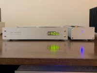
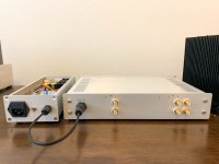
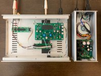
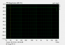
The new zeners arrived along with various damping materials. I replaced the parts and everything is looking good now. I went overboard with damping and there is no ringing now on volume change. I still think my Nutube is overly microphonic, as moving my finger gently on the top of the damping material will cause low (but audible) ringing.
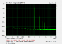
I also had the chance to measure it with my amateur test suite (ARTA+pmillett SCI+EMU soundcard). In my setup, it's measuring ~1% THD with 1V output at the 9.5V bias point. FR is pretty flat, which is nice. If I ever swap in film caps for coupling, atleast I have a good baseline on what sufficient capacitance should look like.
One nice bonus is that the volume display shows -16db at 0db gain (1V in 1V out).. I thought that was cool since the circuit has about 16db of gain.
Really happy with how this came out.. Thanks Nelson!!!
Attachments
to itshikefez #4594
Hello itshikefez,
a very nice build with a clean design! I like it!
Enjoy the sound! Don't forget to play with the 10kOhm trimpots and
try to reverse polarity of your speakers at the poweramp / speakeroutput.
Will be an 'interesting journey' for you - as it was for me...
Perhaps you will need a lot of time to listen to your music / CD's / vinyl
in a new way.
Greets
Dirk
The new zeners arrived along with various damping materials. I replaced the parts and everything is looking good now. I went overboard with damping and there is no ringing now on volume change. I still think my Nutube is overly microphonic, as moving my finger gently on the top of the damping material will cause low (but audible) ringing.
I also had the chance to measure it with my amateur test suite (ARTA+pmillett SCI+EMU soundcard). In my setup, it's measuring ~1% THD with 1V output at the 9.5V bias point. FR is pretty flat, which is nice. If I ever swap in film caps for coupling, atleast I have a good baseline on what sufficient capacitance should look like.
One nice bonus is that the volume display shows -16db at 0db gain (1V in 1V out).. I thought that was cool since the circuit has about 16db of gain.
Really happy with how this came out.. Thanks Nelson!!!
Wow! Beautifull build! Congartulations. Enjoy
- Home
- Amplifiers
- Pass Labs
- B1 with Korg Triode