Carsten,
Sorry I can not help you.I could not find other shops.
I searched Japanese information about Nutube's microphonic noise.
Some people are using cushions, but I can not find a definitive know-how.
But,I found one unique way.
Placing a powerful magnet on the back of Nutube reduces microphonic noise.
1722 :真空管 KORG Nutube、 磁石でマイクロフォニック・ノイズを消す (第2編) | ShinさんのPA工作室
Can you understand with photographs?
When you place the magnets properly, the blue light of Nutube becomes narrow linearly and the sound improves.
The reason for this is presumed that vibration of the filament is suppressed by magnetic force.
(There are other explanations, but translation is difficult for me)
There is no explanation about side effects.
I also ordered the B1 board. I will try this magnet method later.
That is an amazing find. It looks like the harmonic distortion at 10kHz goes from 0.1% to 0.015% (!!!) using either the magnet configuration in photos 1 and 2, while also significantly improving microphonics.
Those who built the Korg preamp and are able to measure distortions.... please place the strong magnet on top of the tube and see if the distortions really drop... also, it would be good to know how is the magnet affecting distortions' characteristics and if the change in plate voltage will still produce a desired distortion signature.
Of course, good-old simple listening impressions will do as well
Last edited:
I down loaded the CAD files for the Galaxy 2U imported them into Rhino3D and played for ages trying to get something that would look good and would work with the boards and got this:
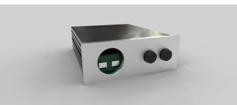
Watched some videos on youtube of guys doing stuff to Aluminium with woodworking tools that seems wrong at every level but felt the fear and did it anyway:
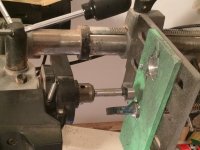
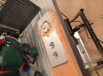
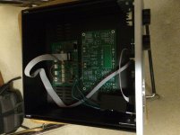
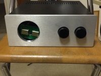
Scary stuff taken slowly with lots of care clamping and WD40
Two boards visible the Korg and the Khozomo at the back. Khozomo led matrix and korg will be visible through the window behind smoked perspex I picked up for $5

Watched some videos on youtube of guys doing stuff to Aluminium with woodworking tools that seems wrong at every level but felt the fear and did it anyway:


Scary stuff taken slowly with lots of care clamping and WD40
Two boards visible the Korg and the Khozomo at the back. Khozomo led matrix and korg will be visible through the window behind smoked perspex I picked up for $5
I think it was a double fluted 6mm Tungsten Carbide. Nothing special just one that looked sturdy enough not to snap off and small enough not to lose speed and bog down. It took a couple of dozen passes and I stopped a few times to clear out the swarf and spray some more oil on it. You tube videos suggest you slow the speed down but I found it worked better with a bit of speed. Too fast and you'd heat everything up. As with circle cutting wood using a router the biggest trick is to ensure the centre of the circle stays put when you break through because it's whats holding the router in position. You'll see in the photo a screw offset from the centre of the circle holding it in place. The result isn't CNC perfect but it's cleaned up with bit of sandpaper in the drill press. I have a bit of dowel with a slot cut into it that I can put strips of sandpaper into to polish things up with. I thought the brushed finish would suffer and kept a sharp eye out for any swarf between the router base and the front. There's a couple of micro scratches that might benefit from being gone over with a scouring pad but not something instantly obvious.
avtech, if you are close, you'll have to come over sometime, I have a few DIY bits in my system. Building speakers next, a Lenehan LK1 kit.
Thanks Batty, drop me a PM which suburb you're in.
I think it was a double fluted 6mm Tungsten Carbide.
How did the Forstener bit fair in ally?
Last edited:
I was very surprised by the forstner bit it made slow but steady progress and did a neat job creating countersinks for the knobs. I put the drill on the lowest speed for that to get some torque as the drill is pretty gutless and the motor stalls given a chance. Guy on Youtube compared using a forstner bit to using a spade drill. The spade drill went through very easily creating big ribbons but left a threaded edge. Forstner bit is smooth cut with a small bur on the top edge.
Four pins socket's so why 3 thru holes are drilled not 4 on the left and right PCB side?
Again one more time: is better to build good working prototype(s) first so no need to apologize
to the hobby amateurs after the bad surprises....

Dear Soundhappy,
May i know why you do this (red circle) in your PCB. I see some people will do this on their PCB.
It is Grounding or about the noise?
Does anyone can tell me how to design audio PCB will better?

Dear Soundhappy,
May i know why you do this (red circle) in your PCB. I see some people will do this on their PCB.
It is Grounding or about the noise?
Does anyone can tell me how to design audio PCB will better?
The many holes is to prevent capacitance between the top and copper layer , I think .
A spent some time playing around with the trimpots...
Started at 9.5V: sound is very 3D and "wet" compared to solid state. I do sense a bit of veiling or fuzziness however.
At 10.5V: Much tighter and more dynamic. Bass is cleaner. But it has somehow turned from 3D to 2D. Not fun anymore. If I want this sound I will use my solid state preamps which are better at this type of presentation.
I turned it down to 9.75V and left it there.
But this may all be dependent on your speaker efficiency, amplifier gain and listening volume.
I think I may need 2 preamps in my life...the B1 Korg and a clean solid state pre.
I think I may need 2 preamps in my life...the B1 Korg and a clean solid state pre.
Why stop at just two?
A spent some time playing around with the trimpots...
Started at 9.5V: sound is very 3D and "wet" compared to solid state. I do sense a bit of veiling or fuzziness however.
At 10.5V: Much tighter and more dynamic. Bass is cleaner. But it has somehow turned from 3D to 2D. Not fun anymore. If I want this sound I will use my solid state preamps which are better at this type of presentation.
I turned it down to 9.75V and left it there.
But this may all be dependent on your speaker efficiency, amplifier gain and listening volume.
I think I may need 2 preamps in my life...the B1 Korg and a clean solid state pre.
Which of your solid state preamps are you comparing with? I recall you built a few.
Are you using a good quality attenuator with the B1K or as good as the ones with your other preamps?
Just trying to understand. Not yet built a B1K but considering it.
nash
- Home
- Amplifiers
- Pass Labs
- B1 with Korg Triode