A bit late to join the party, but at last here is my built ")
First of I would like to express my greatest thanks to Papa / Nelson without whom I wouldn’t have this little pre and whose commitment and sharing is simply amazing. Just for that, and for my listening experience with his Pass amps, I always wanted one of his builts. I would also like to express my greatest thanks to Jim / 6L6 who provided me with outstandingly generous and very kind support, both theoretical and practical, and who gave me the desire through his numerous detailled guides to get DIYing / soldering again… after 15 years of inactivity - shame on me, but if I succeed, then why not « you » ?
Last but not least, big thanks to the numerous contributors on this thread who have been very inspirational, with special mention to ZM who was so kind enlightening me on some « stupid questions ». Oh, and to give you a more personal info : I am short on time, I really don’t need a pre and for sure don’t need any gain (16dB here !) nor wanted caps in my signal path (had so far only 2 in my entire system). But – spoiler - got enthousiastic and it is really fun!
As there are enough examples of the Korg B1 here, with people that are more skilled than I am with a soldering iron or with a camera, not to mention their brain, I will try to contribute my way on different matters. I have bought some extra parts and the plan is to compare some options against each other to hopefully give some hints to enthousiasts who might get started in the future and don’t want to waste time or money trying things out by themselves.
The following posts describe the Korg exactly as intented by Papa, bare the PS that I found interesting for its low ripple this side of the Atlantic and hopefully its ability to cope with more load/ starting surge. So this is the benchmark, per the book really.
The intention is then to compare the 1000uF filtering caps vs 2200uF ones, then to try out a Tocos potentiometer with some measurements and possibly some mods vs more standard potis and a fix soldered resistor set up (the reference). Finaly, I have purchased some very big PP caps to replace those in the signal path. And that’s it… as all that is still in line with Papa’s recommendation / latitude for building this B1 Korg and also because some interesting ideas I had turned out (thanks ZM)… not to be good ones ! Well, apart perhaps from the direct HP line out I intend to have, and with that we covered all what I hope to detail and try out soon, time permiting.
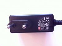
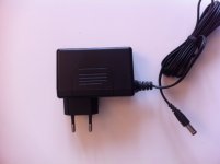
The power supply I (based in EU) have purchased is
MeanWell SGA25E24-P1J
It has a slim form factor, 1.04A rating good regulations specs, is a well known entity, and has a quite low ripple of 80mVpp - but this is just general spec and doesn’t necessarly say something about the sonic quality, but well…
I hope it will perform well with its low ripple while being able to cope with the extra surge when increasing the value of the 3 filtering caps on the board...
Attachments
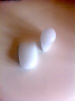
Someone here posted the idea to use silicone toe protections to dampen the underside of the Nutube, obviously with some adhesive. I got 5 pairs of these toe protections for under 4$ on the net and that's how theylooks like.
Let's see how many I will use and if they work - by the feel of it they are quite damping indeed
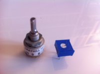
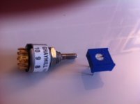
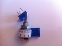
Source switch can be complicated to find as so many options, so here is the shorting one I use, courtoisie of 6L6 Further, source switches can be complicated to find as so many options, so here is the shorting one I use, courtoisie of Jim alias 6L6 who was kind enough to guide me on that aswell
56A36-01-2-03S Grayhill | Mouser
Jim posted already on that, in case the reference wasn't completely explicit here we go again. It is as you can see really a tiny switch, but really cute and well made, with clear contacts and low resistance values.
Sorry for the poor pix
Let's see how many I will use and if they work - by the feel of it they are quite damping indeed
Source switch can be complicated to find as so many options, so here is the shorting one I use, courtoisie of 6L6 Further, source switches can be complicated to find as so many options, so here is the shorting one I use, courtoisie of Jim alias 6L6 who was kind enough to guide me on that aswell
56A36-01-2-03S Grayhill | Mouser
Jim posted already on that, in case the reference wasn't completely explicit here we go again. It is as you can see really a tiny switch, but really cute and well made, with clear contacts and low resistance values.
Sorry for the poor pix
Attachments
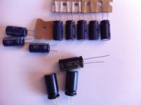
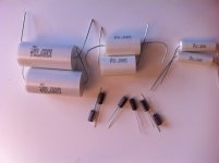
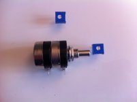
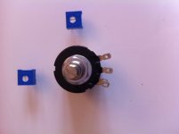
In terms of goodies to test as alternative parts, this is what I have in my bag
I attached 2 pix of a Tocos potentiometer - no clue if that sounds good but is supposed to be an alternative to my beloved Black Beauty while being really non expensive, so worth digging and I purchased one. It is advertised with 5% tolerance and indeed it measures quite OK - more on this and some further ideas to follow.
Next question I have is: is increasing the filtering caps from 1000uF to 2200uF worth doing, despite the low ripple PS? Will it start again with the wallwart supply? I hope to find out soon and to assess in what magnitude the sound changes... or not. Papa encouraged us to play with and likes big caps, so worth assessing for me.
And last but not least, the usual cap in the signal path debate. On one side the recommended ones, on the other big PP. Hope also to do before / after comparison and stick to the best option, as sound preference only matters and I have all parts anyway.
That is the plan, of course if and when I get first my 'standard' B1 Korg to work properly...
Attachments
Progress are slow on my side as only able to work when the rest of teh family is away the WE or in bad late night... small fingers are my enemy
To be honest, built is straight forward: just follow Papa's instruction and read 6L6's built guide. Nothing more to say, this should be an easy one. Can't say yet if mine works, but assembling and soldering was really straight forward despite me being rusted on all this.
A few pix of my progress and a few notes, well bearing in mind that you are better off taking advices from Jim / 6L6 then taking example on me!
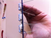
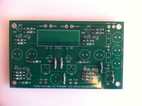
So I started as usualy with the smallest parts, the resistors and the diode. I took then some blu-tack like stuff for the big "power" resistors to solder them slightly lifted to air can circulate. Was only needed for 2 of them, the 10R ones, but it looked better if doing the entire row
I then went on soldering the trim pots. The 10k ones I found don't have the same footprint and pin spacing, so that required a bit of leg bending. Scary, but they do take more abuse then I thought, so adjusting and pressing slightly down worked for me.
To be honest, built is straight forward: just follow Papa's instruction and read 6L6's built guide. Nothing more to say, this should be an easy one. Can't say yet if mine works, but assembling and soldering was really straight forward despite me being rusted on all this.
A few pix of my progress and a few notes, well bearing in mind that you are better off taking advices from Jim / 6L6 then taking example on me!
So I started as usualy with the smallest parts, the resistors and the diode. I took then some blu-tack like stuff for the big "power" resistors to solder them slightly lifted to air can circulate. Was only needed for 2 of them, the 10R ones, but it looked better if doing the entire row
I then went on soldering the trim pots. The 10k ones I found don't have the same footprint and pin spacing, so that required a bit of leg bending. Scary, but they do take more abuse then I thought, so adjusting and pressing slightly down worked for me.
Attachments
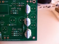
Then I disgressed somewhat from the usual recommandations. Before doing the transistors and smaller caps, I put some big caps in place on all corners so when reversing the board it could rest on my table on these caps and be stable... I found it useful when installing the other tiny and fragile parts. This applies obviously to this built only with caps at extremities.
For the transistors, I simply pushed them in place carefully and soldered them directly from teh back.
As for the small caps, I used Blu-tack aswell to hold them in place, but that was because I didn't want to bend their legs - I intend to solder them in and out, so straight short legs will be easier to undo while being hopefully more board friendly.
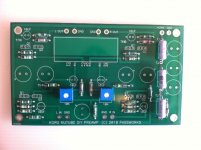
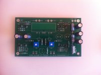
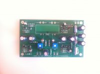
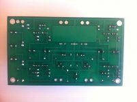
And here we go, the board with all parts - bare the Nutube. That's as far as I went for now, as sadly my expected Nutube never materialised. Not a problem, if you are based in France you can order it quite reasonably from RS - that's what I did, and I expect it to arrive soon.
If you see anything wrong, please shout! I am running out of time but will go through the thread again as I believe I can connect the board to the PS with the potentiometer as load and check some voltages to make sure all is right before installing the Nutube. I will do that... as soon as I get some time again.
Sorry for the long posts, I hope not too boring
Claude
For the transistors, I simply pushed them in place carefully and soldered them directly from teh back.
As for the small caps, I used Blu-tack aswell to hold them in place, but that was because I didn't want to bend their legs - I intend to solder them in and out, so straight short legs will be easier to undo while being hopefully more board friendly.
And here we go, the board with all parts - bare the Nutube. That's as far as I went for now, as sadly my expected Nutube never materialised. Not a problem, if you are based in France you can order it quite reasonably from RS - that's what I did, and I expect it to arrive soon.
If you see anything wrong, please shout! I am running out of time but will go through the thread again as I believe I can connect the board to the PS with the potentiometer as load and check some voltages to make sure all is right before installing the Nutube. I will do that... as soon as I get some time again.
Sorry for the long posts, I hope not too boring
Claude
Attachments


Pass DIY Addict
Joined 2000
Paid Member
Remember that the plate of the tube is a high impedance spot, and is happy to
pick up on unshielded noise. If the chassis is not grounded, it becomes part
of the problem.
I double checked the grounding and even added a jumper from the PCB to ground at a few test points - this didn't make any difference in the noise that I was hearing in one channel.
You're torquing the board differently and opening up less pristine solder joints?
Turns out this was my problem. With the board on the metal standoffs, everything was fine but with the board on rubber washers, I got noise from one channel. A visual inspection didn't reveal obvious problems, so I reflowed all of my solder joints and the noise problem went away.
Thanks for the help, now I've got nothing but beautiful music from my B1 Korg!
I double checked the grounding and even added a jumper from the PCB to ground at a few test points - this didn't make any difference in the noise that I was hearing in one channel.
Turns out this was my problem. With the board on the metal standoffs, everything was fine but with the board on rubber washers, I got noise from one channel. A visual inspection didn't reveal obvious problems, so I reflowed all of my solder joints and the noise problem went away.
Thanks for the help, now I've got nothing but beautiful music from my B1 Korg!
Great to hear that you’ve got it fixed! 👍🏻
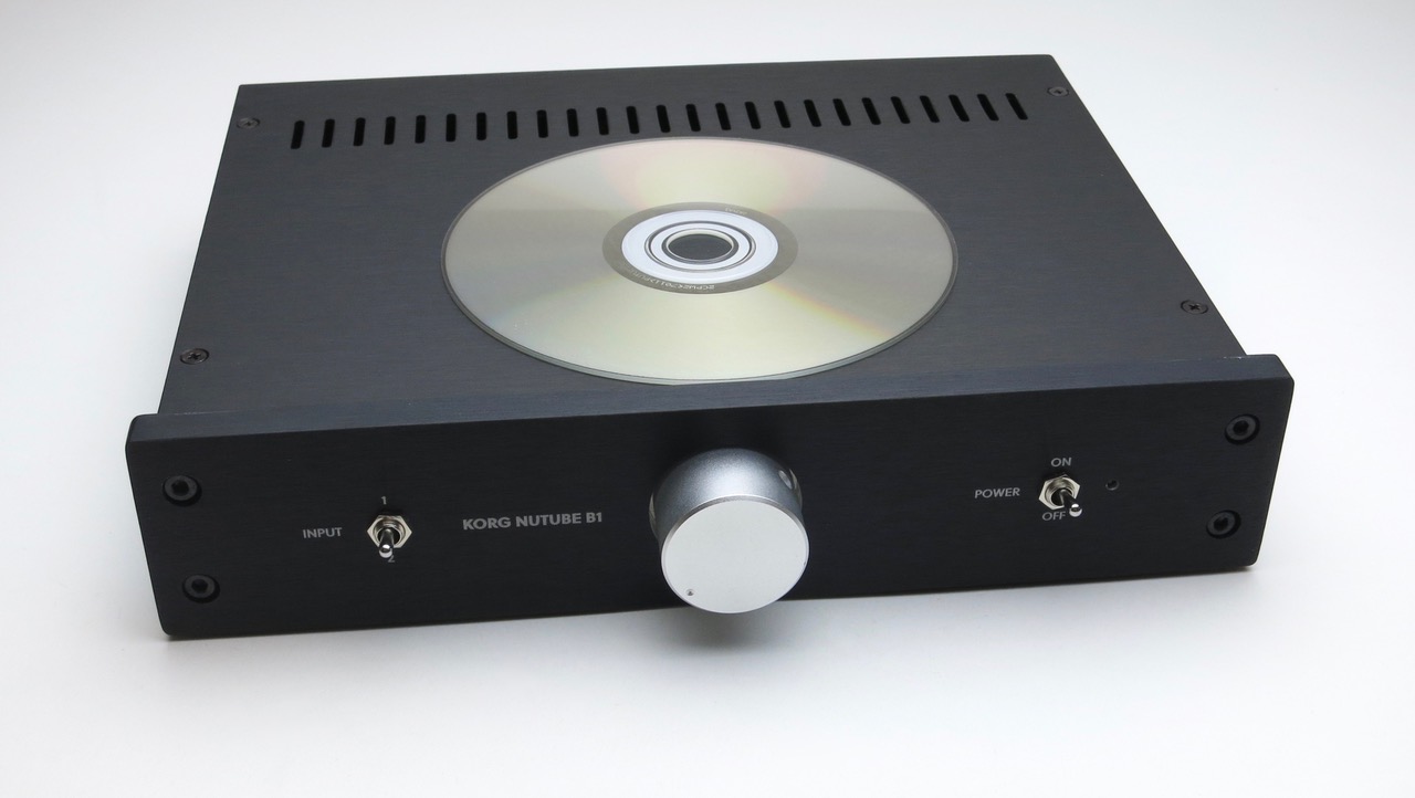
Prototype Store Chassis
Here are some photos of the Prototype store chassis, it's about 98% correct, there's a couple layout issues that will be corrected (move all the holes a bit to the right, move the PCB more towards the center, etc...) but generally this is what it will look like - and I think it looks great!
There will also be a parts kit available, similar to what's shown but not exactly what's seen here. Will be similar or better.
Timeframe? Soon(ish)
I am interested in a parts kit so that I can make ACA a hybrid. Just wondering if I need to take time off of work to watch the store when it goes on sale.
waiting for the official case!
while doing tests in naked mode, perfect performance, just great.
https://i.imgur.com/iHqfz5G.jpg
here in tests with a ICEpower amp:
https://i.imgur.com/gXr4eKA.jpg
while doing tests in naked mode, perfect performance, just great.
https://i.imgur.com/iHqfz5G.jpg
here in tests with a ICEpower amp:
https://i.imgur.com/gXr4eKA.jpg
Here are some photos of the Prototype store chassis, it's about 98% correct, there's a couple layout issues that will be corrected (move all the holes a bit to the right, move the PCB more towards the center, etc...) but generally this is what it will look like - and I think it looks great!
There will also be a parts kit available, similar to what's shown but not exactly what's seen here. Will be similar or better.
Thanks so much for your efforts! I agree that it looks gorgeous!
Missing transistors?
I have started building the B1 Nutube, but have become confused about the number of transistors. With the Diyaudio kit, I received a total of 4xQ1 plus 4xQ2 with 4 resistors. However on the print are marked for a total of 8xQ1 and 8xQ2.
Whats wrong? I cannot find mention of this in neither this thread or Nelsons paper?
You can find it in page three of the paper (see the picture
):http://www.firstwatt.com/pdf/art_diy_nutube_preamp.pdf

- Home
- Amplifiers
- Pass Labs
- B1 with Korg Triode