Hey Dirk,Hello ChrisM91,
I have mounted 10-turn pots into my B1 NUTUTBE. I have prolonged from the pcb to the trimpots.
Works like a charm. I have to look for the pics of my B1NUTUBE
I did the same in my H2-generator... but with two 270 degree-pots to adjust H2 (pos.-neg.).
Cheers
Dirk
Do you find the bias drifts much on the B1K?
Do you find yourself adjusting the pots to get different tones very often?
Hello Chris,
I don't have the experience with bias drift - if, then in very small increments.
In the beginning I played a lot with those settings. But then I found an adjustment point to my 'listening taste'.
And I didn't like to adjust it to the extremes.
And I play with different configurations ( Changing the poweramp;...), then I readjust to my liking.
A nice toy!
Cheers
Dirk")
I don't have the experience with bias drift - if, then in very small increments.
In the beginning I played a lot with those settings. But then I found an adjustment point to my 'listening taste'.
And I didn't like to adjust it to the extremes.
And I play with different configurations ( Changing the poweramp;...), then I readjust to my liking.
A nice toy!
Cheers
Dirk
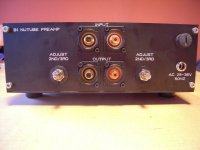
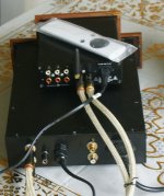
Hi guy's, i have just completed my kit of a double two box system with the top control unit running a PGA2310 Vol Control. It has 4 input 3 RCA & one Blue-tooth, with select & Vol remote
Cheers
Cheers
Attachments
Last edited:
What was your original setting? 9.5?Has anyone tried replacing the stock trimpots with "nicer" multi turn pots?
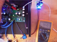
I opened my B1K after enjoying it for 6 or so months and I noticed the bias had shifted a bit (moving closer to 10V on T7/T8). The stock trimpots arent multi turn so they are super sensitive I find.
I arrived at 12V after distortion measurement and listening. I think 11.5V is where 2nd harmonic cancelation happens.
I've always had my B1K at 9.5V. I have never tried anything different.What was your original setting? 9.5?
I arrived at 12V after distortion measurement and listening. I think 11.5V is where 2nd harmonic cancelation happens.
Is there an audible noticable difference in different bias settings?
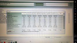
This is my distortion measurement. From 9V to 12V. At listening level. I found too much distortion at 9.5V. At 11.5V I see lowest distortion, then rising again. At 12V you get negative 2nd harmonic, according to others, i do not meassure that, but thats what many prefer. Cheers.
Having a bit of an issue with the voltage adjustment. Noticed this thing started to sound a bit off so I checked the voltages. The cathodes are perhaps a little high.. .65 on the right and .67 on the left. The main issue is the right channel the voltage for t8 is way too high.. I can’t adjust it below 13.5V. T7 is completely fine and rock solid at the 9.5 I set it to when I built it.
Any thoughts?
Any thoughts?
T5 and T6 are the filament voltages of the two channels, and 0.65V and 0.67V are within specifications. So the Nutube filaments seem are ok.
The 10k pot adjusts the grid voltage which varies the anode voltage (T7, T8). So I assume the voltages were within specifications when it was built but now T8 is now high and cannot be adjusted lower. That suggests the right channel Nutube is not conducting enough. So perhaps it has gotten weak, or perhaps some of the solder joints (around the pot, tube, resistors in the area) are not so good.
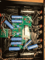
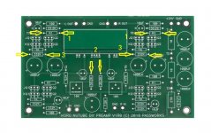
Post some high definition, focused pictures of both sides of the board.
Check the solder joints of the right channel in the area of the Nutube and pot and redo any suspicious looking joints.
The 10k pot adjusts the grid voltage which varies the anode voltage (T7, T8). So I assume the voltages were within specifications when it was built but now T8 is now high and cannot be adjusted lower. That suggests the right channel Nutube is not conducting enough. So perhaps it has gotten weak, or perhaps some of the solder joints (around the pot, tube, resistors in the area) are not so good.
Post some high definition, focused pictures of both sides of the board.
Check the solder joints of the right channel in the area of the Nutube and pot and redo any suspicious looking joints.
Check the solder joints of the right channel in the area of the Nutube and pot and redo any suspicious looking joints.
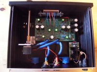
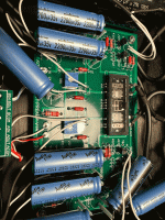
Thank you for replying back so quickly Ben. I checked the solder joints, everything looks good visually. Note that this a rather modified unit, sort of took the "best of" from the earlier pages of this thread with upgraded caps and resistors in critical places. Because this thing is packed like sardines, it is hard for me to get a picture of the underside of the board without really taking it apart, but I have attached a picture of the top side. I was able to look on the underside and like the top, everything appears ok, nothing loose, broken, or stray bits of solder causing trouble.
Yes, you are correct, it was running perfectly fine for quite some time, with the voltages adjusting easily as they should on both channels.
Anything else you think it might be before I order a nu-nutube? I have to assume the JFETS are probably more reliable than the nutube. (I also do not know if they would show the same issue if one did fail)
Attachments
Here are a few things that you can check:
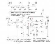
1, At position 3, check the solder joints of the 332k resistor. Measure the voltage drop across the resistor of both channels. Confirm the resistance. Lift one lead if necessary to measure the resistance.
2. At position2, measure the voltage at the 33.2k resistor relative to ground for both channels. For the bad channel, does the voltage change when you adjust the trimmer pot? What voltages do you get?
3. At position 1, measure the voltage drop across R1 of both resistors. If the JFETs are working properly, the voltage should be the same for both channels.
Attachments
Ben,
The help and diagrams are very much appreciated!
1) Measured 11.2V across the good channel, 7.2V across the bad channel. Resistor on the bad channel measured 332K.
2) Measured 2.47V on the good channel (set at 9.5V on T7), 2.89V down to 0V on the bad channel. (the VFD was dark when it was down to zero, and glows very bright when its at 2.89, the same pot position as the lowest voltage for T8)
3) Measured 1.7V on the good channel, 1.6V on the bad channel.
Starting with 3), the difference between channels is small so I would say that the output JFET buffer is working properly.
As for 2), the bias adjustment is working properly.
And 1), the 332k load resistor resistance measured correct. The reduced voltage drop across the resistor is because of less current through the resistor than normal.
I assume that the voltage at T8 varied as the bias pot was adjusted since the glow of the Nutube varied also. The glow is the Nutube plate as current flowed.
As far as I can tell, the circuits surrounding the Nutube are working correctly, so unfortunately it points to a bad channel in the Nutube. The bad channel is still functioning but not at full strength, as its current output is reduced.
I havent yet applied any real tweaks (besideds the SMPS DC Filter P089ZB Kit) witch i applied from day one.
But i would like to report that i have been running the B1 this week between my external USB D/A from the computer and my small black Genelec all aluminium 2.1 system, the studio monitors working at my office, at work.
Well, the Genelecs (Fully active, small A/B amplifiers to every separare element) are utterly ”perfect”, very balanced, neutral and kindly forgiving.
They are so perfect that it can make them sligtly boring at times. A little bit to often Uninterestingly ”perfectly” balanced.
Well?
And now with the B1 in the mix: Bone stock. It brings a little amount, not really little, but just the right amount of more juice, life!, and musical joy and interesting exitement! to it all. I simply love it! 🎷🙂🎸
Hard to explain, but there it is. In my opinion. 🙂🤚
JayDee, isn't exciting to play with new toys? I had put my Korg B1 away for a while and just recently pulled it out. it is very nice to experience it all over again.
Adason's # 7889 is a good one for getting an idea on how to play with the sugar dial. Also, flipping the leads on your speakers, red to black, black to red will give another effect. Just some more things to play with
Adason's # 7889 is a good one for getting an idea on how to play with the sugar dial. Also, flipping the leads on your speakers, red to black, black to red will give another effect. Just some more things to play with
This is my distortion measurement. From 9V to 12V. At listening level. I found too much distortion at 9.5V. At 11.5V I see lowest distortion, then rising again. At 12V you get negative 2nd harmonic, according to others, i do not meassure that, but thats what many prefer. Cheers.
Yes
More or less sugar, depending on bias.
And positive or negative H2 setting.
Try it, it is fun
Claude
So I got around to playing with the bias tonight. Brought T7/T8 up to 11.5V and got them stabilized at this level.
At 11.5V I find the soundstage more interesting and lively for lack of better words. Can't say I notice a difference in distortion or noise but my ears arent that good and I think from your data adason were talking a few %.
Thanks lads!
- Home
- Amplifiers
- Pass Labs
- B1 with Korg Triode