I feel like those wires aren’t twisted, but it’s just a pattern printed on the outer sleeve. @rmpfyt is that the case?@rmpfyf
I don't understand why you used single twisted pair for L & R signal and another single twisted pair for signal ground of L & R on input RCA, that is conceptual wrong.
Twisted pair should carry only left (or R) hot and signal GND, other twisted pairs should be for rest of the RCA connectors. Twisted pair have function to minimize interference picked from nearby wiring. Is your case grounded? don't see well what type of power socket it is, is it isolated from case? If not isolated then you have power GND connected to the case and you form protection from outside RF signals or interference. Is your case anodized aluminum? If yes, then you should on some way enable good electrical connection between parts of the case to comply Faradey cage.
Attachments
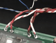
I feel like those wires aren’t twisted, but it’s just a pattern printed on the outer sleeve. @rmpfyt is that the case?
Those wires have a weird patten on them and yes, the +/- pairs are lightly twisted. I ran out of skill with the supplied Ethernet core, so I grabbed what I had handy... wouldn't imagine that's the cause of this interference?
Would it help if I uploaded some MP3's of the actual sound?
Didn't mean on output in my post, I meant on input, look on the picture, you will see what I wrote.
I understood you - just followed what was written in the build guide (did I mess that up?)
Admittedly in retrospect what I've done is not best practice.
Look better what is grounded, on PCB there are some points which may be grounded to the chassis (case) and your power input connector too.
So, maybe you have ground loop which may introduce some strange noise (unwanted audio).
You did mess up for sure input wiring. Output wires will not have much influence on your problem.
Try to check that your input connectors do not have connection to the chassis (normally when ground wires unsoldered).
Who placed these pictures, what is your reference to build your Korg, do not know much about signal and return path. I suggest that you try what i suggested.
You will for sure get better L-R separation. You don't need connection between RCA gnd, they will be connected together on input switch selector. What is on the picture will have some sense if input RCA were in function with balanced input but that is not the case in this build. This build have two unbalanced input with switch input selector to select which input will be used.
You will for sure get better L-R separation. You don't need connection between RCA gnd, they will be connected together on input switch selector. What is on the picture will have some sense if input RCA were in function with balanced input but that is not the case in this build. This build have two unbalanced input with switch input selector to select which input will be used.
Who placed these pictures, what is your reference to build your Korg, do not know much about signal and return path. I suggest that you try what i suggested.
You will for sure get better L-R separation. You don't need connection between RCA gnd, they will be connected together on input switch selector. What is on the picture will have some sense if input RCA were in function with balanced input but that is not the case in this build. This build have two unbalanced input with switch input selector to select which input will be used.
You're right.
I followed the official build guide linked earlier. I may have made a mistake (but I can't see where honestly - on that guide the L/R pos come off a twisted pair, which seemed strange but I didn't argue). I have enough wire to redo that.
I don't feel that will solve the interference issue, and I'm feeling I've a**ed up the ground somewhere. The two screw points on the PCB to front of case appear to be grounded through the case, though making that work properly... worth pulling out the MM to check continuity.
Look at this pic
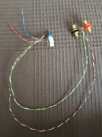
Blue/white-blue will go to input of the board, Orange/white-orange will go to another RCA input (other channel not attached to better understand the pic), all white-any color are connected together at switch side as you can see.
As you can see single twisted pair will carry one channel (green/white-green = L left channel & brown/white-brown = R right channel), white-green, white-brown and white-blue are tied together, alternative is to use another pair of switch to switch signal ground, but I do not prefer that. If you have spare switch contacts you can do that and isolate signal ground of second RCA input.
I took this pic to clarify your error.
Please check is your power connector with minus pol connected to the chassis, simple switch off unit on the switch and measure if you have connection to the chassis. If you have that connection that is your ground loop. With switched off unit measure do you have connection between signal ground and chassis, if yes then you have your board grounded and you don't need another join to the chassis, that is your ground loop and you will probably loose your unwanted noise.
Regards,
Attachments
Add on to previous post, what I meant with input, is connection to the volume pot AIN and ACOM (or second BIN and BCOM) and from AOUT and ACOM you will go to the input on the board.
White-any color will go to the ACOM and BCOM, you can split white-any color near the switch so only one channel will go to ACOM and BCOM respectively.
White-any color will go to the ACOM and BCOM, you can split white-any color near the switch so only one channel will go to ACOM and BCOM respectively.
Hi folks,
Not trying to hijack this thread, but thought this might be better to ask my question here rather than start a new one (unless starting a new thread is recommended).
I just finished up building my second Korg Nutube Triode in which I had sourced most of the parts from Digi-key.
Only parts purchased through the DIY store were the transistors with matched resistors and the Alps volume control PCB add-on board.
Here's the problem I'm having.
All my voltages are great except for the adjustment of the two 10k trimmer pots.
I couldn't find the 10k trimmer pots supplied in the kit sold by the DIY store so I substituted these Bourns Inc.
10k ohm 0.5w pc pin top. (see link below)
https://www.digikey.com/en/products...1088425?s=N4IgTCBcDaIMxwGxgE4EYAMcA2AzEAugL5A
No mater what I do with the trimmer pots the voltages remain up around 16v.
When making adjustments on the trimmer I do see the Nutube dim and brighten, but the voltages just about remain constant.
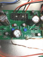
I also noticed that the transistor on the right (shown by the red arrow) temp is hovering around 138-f and all others around 80-f.
Any help from the Guru's would greatly be appreciated in helping me sort this out.
Kind Regards,
Not trying to hijack this thread, but thought this might be better to ask my question here rather than start a new one (unless starting a new thread is recommended).
I just finished up building my second Korg Nutube Triode in which I had sourced most of the parts from Digi-key.
Only parts purchased through the DIY store were the transistors with matched resistors and the Alps volume control PCB add-on board.
Here's the problem I'm having.
All my voltages are great except for the adjustment of the two 10k trimmer pots.
I couldn't find the 10k trimmer pots supplied in the kit sold by the DIY store so I substituted these Bourns Inc.
10k ohm 0.5w pc pin top. (see link below)
https://www.digikey.com/en/products...1088425?s=N4IgTCBcDaIMxwGxgE4EYAMcA2AzEAugL5A
No mater what I do with the trimmer pots the voltages remain up around 16v.
When making adjustments on the trimmer I do see the Nutube dim and brighten, but the voltages just about remain constant.
I also noticed that the transistor on the right (shown by the red arrow) temp is hovering around 138-f and all others around 80-f.
Any help from the Guru's would greatly be appreciated in helping me sort this out.
Kind Regards,
Attachments
Hi Benjisan, Sorry to see that you have problems.
Since adjustment of the trimmers affected the Nutube, the trimmers are probably working. But to check, measure the voltage at points that I marked as "E" relative to Ground and "F" relative to ground as you adjust the trimmers. The voltage should vary with adjustment.
Since you purchased the JFETs from the diyAudio Store I assume that the JFETs are J113. Are all four resistors that came with the JFETs the same value? And what is the value?
The next check is to measure the voltage drop across each of the R1 resistors that I marked "A", "B", "C", and "D". If the resistors are the same value, the voltage drop across each resistor should be more or less equal. And the Voltage/Resistance should be between 0.004A and 0.008A.
Hi Ben,
Thanks for jumping onboard as I really do appreciate it...
I'm sure it's something very simple, but I'm not versed enough in the right trouble shooting steps to take and narrow it down.
I posted a bunch of pictures to better illustrate the voltages I'm seeing.
The first picture is the resistor value reading from the 4 supplied R1's that were included with 8 jfets within the DIY store Nutube kit in picture two.
The 17.01 v and 16.98v is taken from the leg of the 1K resistors.
I didn't get any voltage variation when adjusting the 10k trim pots from either side of the 1K resitors at all.
R1 by T7 measured 1.231 volts and R1 by T8 measured 1.272 volts.
R1 by T5 measured 00.8 millivolts and R1 by T6 measured 0.13 millivolts.
Are the discrepancies between the two sections of R1 voltages the issue at hand?


 — Sc...png")
Thanks for jumping onboard as I really do appreciate it...
I'm sure it's something very simple, but I'm not versed enough in the right trouble shooting steps to take and narrow it down.
I posted a bunch of pictures to better illustrate the voltages I'm seeing.
The first picture is the resistor value reading from the 4 supplied R1's that were included with 8 jfets within the DIY store Nutube kit in picture two.
The 17.01 v and 16.98v is taken from the leg of the 1K resistors.
I didn't get any voltage variation when adjusting the 10k trim pots from either side of the 1K resitors at all.
R1 by T7 measured 1.231 volts and R1 by T8 measured 1.272 volts.
R1 by T5 measured 00.8 millivolts and R1 by T6 measured 0.13 millivolts.
Are the discrepancies between the two sections of R1 voltages the issue at hand?
Last edited:
1.23V and 1.27V across the 150R are good, approximately 8mA.
0.8mV and 1.3mV are not good and will need to be looked at. But it should not affect the issue of the trimmer not having any effect on the Nutube.
To continue with the trimmer issue, please measure the voltage relative to Ground at the two points indicated on the pcb. The voltage should vary when the trimmer is adjusted.

Also please measure the voltage across the 33.2K resistor.
0.8mV and 1.3mV are not good and will need to be looked at. But it should not affect the issue of the trimmer not having any effect on the Nutube.
To continue with the trimmer issue, please measure the voltage relative to Ground at the two points indicated on the pcb. The voltage should vary when the trimmer is adjusted.
Also please measure the voltage across the 33.2K resistor.
Last edited:
Hi Ben,
The 33.2K resistors when referenced to ground for both 10K trimmers become variable and can adjust up or down on the voltage. I set both 10k trimmers to 9 volts and I noticed that right hand side of the triode near T-8 has a much brighter blue glow than the other side near T-7
When measuring voltage directly across each of the two the 33.2K resistor individually I'm seeing between 00.1 mv and 00.5 mv as it is fluctuating between those two values.
I hope there's a clue in those numbers. I also lifted the board and I'm not seeing any solder bridges on either side.
Last edited:
Adjusting the trimmer varied the voltage at the end of the 33.2K resistor is good news. The voltage at the end of the 33.2K resistor is the Nutube grid voltage. As there was voltage drop across the 33.2K resistor, that is good too, indicating that there was grid current. So the bias circuit seemed to be working.
You mentioned previouly that this is your second B1 Nutube. What is the Nutube grid voltage on your other B1 Nutube? Around 2V?
So before you make further measurements, adjust the trimmers so that the grid voltage of both channels is less than the grid voltage of your other B1 Nutube.
Measure the voltage at T5 and T6 relative to Ground. It should be about 0.6V. Voltage drop across the 475R resistors next to T5 and T6 should be about 8.4V for correct filament current. A filament current that is too high may be the cause of the brighter Nutube channel. Another possible reason for one channel appearing brighter is that the brighter channel had a much higher anode current. The higher the grid voltage, the higher the anode current, and 9V grid voltage is very high. Too much anode current and/or too much filament current are both bad for the Nutube.
Also measure the voltages at T3 and T4, which should be 23V and 9V respectively, to make sure the power supply voltages are correct.
So if the power supply voltages are good, if the bias circuit is working properly, and the filaments are working properly, then the Nutube needs to be checked.
Previously, voltage at 1K/332K (anode voltage) at roughly 17V meant that there was current flowing through the Nutube, anode to cathode, which is good. However not being able to go lower than 17Vis not good.
With two meters, one to measure the grid voltage and the other to measure the anode voltage of one channel at a time, use the trimmer to set the grid voltage to the same voltage as your other B1 Nutube, and measure the anode voltage. Is it the same as your other B1 Nutube? Increase the grid voltage. As you increase the grid voltage, does anode voltage decrease? Report measurements for both channels.
Also please check that the 332K resistor next to the 1K resistor is the correct value. Check both channels.
Ben, that was it....
I have made an error in my purchase of parts from Digi-key and installed six NTE 332 ohm 1% resistors instead of the correct 332K 1% resistors.
See pics below.
Now I'm going to have to scramble and try to find some replacement resitors that can be delivered before Christmas as this second Korg preamp is a present for my brother. I just hope I didn't damage anything while testing and trying to fiqure out what was wrong.
Also I want to say a BIG thank you for your kindness, knowledge, and the patience for sticking with me in order to figure this bone head mistake of mine out.


Benjisan, it's good that you found the problem. I too hope that the very high current did not damage the Nutube......
R1 by T7 measured 1.231 volts and R1 by T8 measured 1.272 volts.
R1 by T5 measured 00.8 millivolts and R1 by T6 measured 0.13 millivolts.
Are the discrepancies between the two sections of R1 voltages the issue at hand?
.......
1.23V and 1.27V across the 150R are good, approximately 8mA.
0.8mV and 1.3mV are not good and will need to be looked at. But it should not affect the issue of the trimmer not having any effect on the Nutube.
..........
The issue of the low voltage drop across R1 by T5 and T6 still needs to be addressed. Such low voltages indicate that practically no current is flowing through the JFETs at the front end. The voltage across R1 by T5 and T6 should also be about 1.25V. Since the JFETs and R1 resistors all came from the diyAudio as a package and the set at the output works, I suspect that the set at the input should also work, and that the problem is caused by something else. Perhaps you have another resistor value issue. Please check the value of the 4 - 332K resistors at the bottom of the board and also the R1 resistors, which should be 150R. Also check solder joints of the resistors and JFETs.
Benjisan, it's good that you found the problem. I too hope that the very high current did not damage the Nutube.
The issue of the low voltage drop across R1 by T5 and T6 still needs to be addressed. Such low voltages indicate that practically no current is flowing through the JFETs at the front end. The voltage across R1 by T5 and T6 should also be about 1.25V. Since the JFETs and R1 resistors all came from the diyAudio as a package and the set at the output works, I suspect that the set at the input should also work, and that the problem is caused by something else. Perhaps you have another resistor value issue. Please check the value of the 4 - 332K resistors at the bottom of the board and also the R1 resistors, which should be 150R. Also check solder joints of the resistors and JFETs.
Hi Ben,
Thanks for the further follow up.
When I realized that I had made a mistake and misread and ordered the wrong resistors----> 332 Ohm, and not the 332 K resistors. I also verified that the others resistors (1k, 33.2k, 100 Ohm and 475 Ohm) were correct since I was going to be placing an order over at Digi-key for the 6 correct resistors.
Also I already de-soldered the six 332K resistors from the board earlier when you pointed out that I should check them to make sure they were of the correct value.
I could go over R1 resistors solder joints, JFETs and other resistors, but would I still be able to conclude any futher testing with the six 332K resistors not being populated in the board?
- Home
- Amplifiers
- Pass Labs
- B1 with Korg Triode