Thanks - I will look into it.
H
The 10 kohm at series with " in" to the output pin not after.
That's odd, but not wildly so, as they are just higher Idss than the usual
J113, and there is some overlap there.
Go ahead and use them, they're just constant current sources anyway,
and we are looking for about 6 mA current. You can check that by the
drop across the Source resistors. If the V/R on them is greater than
7 mA, I'll send you replacements.
Hi,
Before listing my measurements, I should mention that I received the Jfets in two bags. One hand marked Q1 7.4, the other Q2 7.4. The resistors that were included were 220 ohm.
I measured across R1 at the four positions. These were my readings:
Ten o’clock (J113): 1.65 V —> 7.5 mA
Two o’clock (J112): 1.64 V —> 7.45 mA
Four o’clock (J112): 1.62 V —> 7.36 mA
Eight o’clock (J112): 1.63 V —> 7.41 mA
The rest of the circuit, after about 75 minutes, adjusted, everything very stable:
T1= 24 V
T2= 23.2 V
T3= 22.4 V
T4= 9.28 V
T5= 0.66 V
T6= 0.66 V
T7= 9.50 V
T8= 9.50 V
I have not listened yet, maybe tomorrow.
Thanks.
7 mA or a bit more is not a problem, but you are welcome to some
replacements. Alternatively you can raise the resistor value.
There are large piles of Jfets laying around, and probably the 112's got
swept into a "retest" bin with all the others whose Idss was greater
than 7 mA. Same chip, these are used for constant current sources.
replacements. Alternatively you can raise the resistor value.
There are large piles of Jfets laying around, and probably the 112's got
swept into a "retest" bin with all the others whose Idss was greater
than 7 mA. Same chip, these are used for constant current sources.
I have a Raal 140-15D ribbon driver with a built in ribbon transformer so that the amplifier doesn't see 0 ohm. It acts like a coil in the crossover so I just have to add a cap to get a 2nd order passive crossover. But how do I reverse poles on a Raal that has this built in transformer/coil without screwing up the passive crossover?
if your goal is to reverse phase of speaker output , it's simple as reversing speaker wires
it's really irrelevant where series cap is situated - in "+" or in "-" side
It might be a wise move to use the J113 for the CCS position while saving the for 2SK170 for the use as the follower.
A very good suggestion. Leave the 7-8 mA figure as is if you do.
Or do nothing - Q1 is simply supposed to have Idss a little larger than
than the CSS, and these would have been 8+ mA Q1's.
A very good suggestion. Leave the 7-8 mA figure as is if you do.
Or do nothing - Q1 is simply supposed to have Idss a little larger than
than the CSS, and these would have been 8+ mA Q1's.
Thank you again for your prompt reply.
From what I am understanding from the last few posts, I have four options:
1 - Do nothing. Easy, that is how I will start. But I am curious as to the effects of this slightly higher current on the circuit.
2 - Replace the Q2 Jfets. Easy, as I have the Jfets in sockets.
3 - Replace the R1 resistors with slightly higher values to bring the current down to around 6 mA. With my limited understanding of Ohm’s law in a circuit, I calculated the new R1 at 270R or 275R. As I understand it, this would also bring the circuit back to design spec.
4 - Leave Q2s and R1s as they are and remove the J113s in the JQ1 positions and replace with matched K170s in the KQ1 positions. I have some matched pairs at 7.09 and 7.12 and a matched quad at 8.88. From what I understand, these values are either a bit too low or a bit too high. But if I bring the current down to around 6 mA, then I could use the lower value pairs. Would this setup have any theoretical benefits over options 2 and 3?
I have built up the board with the parts listed in the most recent First Watt article in order to start with a reference build. I am guessing that options 2 and 3 will get me back there, and option four might be an interesting thing to try as a next step.
A final quick question: what is the impact of having T5 and T6 at 0.66 V vs. the target of 0.6?
Presumably higher voltage of Cathodeheater gives you more Plate
current, although Korg's documents don't comment on it.
The rated current is at .7V at 17 mA, and they recommended a 470 ohm
series resistor for a 9V reference. Since we have a 9.1V zener and a
475 ohm resistor, I presume we are close to their numbers - your .66V
would be 17.7 mA
They warn that when the Cathode glows red you will have a short tube life,
and their example was 25 mA heater current.
So I am posting this to help others.
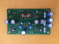
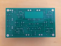
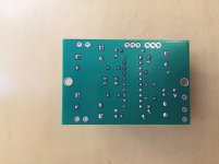
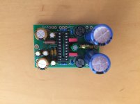
I am finished soldering my boards (mostly). The case is a longer process, so I will complete in the future. The pictures are attached.
Here’s the take away. I previously made attempts at electronic soldering. I failed and gave up multiple times. Though there’s no guarantee I didn’t cook a component this time around. I credit my success to two variables. I was using a generic soldering iron and silver solder in the past. Using the proper tools and supplies is critical for a novice I would say.
Attachments
Looks good Pat, very neat work.So I am posting this to help others.
I am finished soldering my boards (mostly). The case is a longer process, so I will complete in the future. The pictures are attached.
Here’s the take away. I previously made attempts at electronic soldering. I failed and gave up multiple times. Though there’s no guarantee I didn’t cook a component this time around. I credit my success to two variables. I was using a generic soldering iron and silver solder in the past. Using the proper tools and supplies is critical for a novice I would say.
Stick with it - I fried a couple of components on the way but it worked out in the end. Having a decent, controllable soldering station really helped - a worthwhile investment for me anyway.
Let us know what happens when you power it up.
H
I picked up my board and jfets from my local posy office after paying the requisite fees; soldered all the components to the pcb yesterday and tested this morning. Happy to say that no magic smoke was released and all voltages are within a fraction of those listed. It is powered by


Last edited:
Just another Korg Nutube DIY preamplifier example MJ1904_(05)Nutube-hyhbrid-MC-preamp_KanedaA.pdf - Google Drive 
Just another Korg Nutube DIY preamplifier example MJ1904_(05)Nutube-hyhbrid-MC-preamp_KanedaA.pdf - Google Drive
Yes, its the Kadena No 251
it's Kaneda n° 264 ....
Oups
Yes it is noted on the first page.
His first nutube preamp was No251.
A+
- Home
- Amplifiers
- Pass Labs
- B1 with Korg Triode