There are many Members who won't listen to the advice they don't like.
But worse, there are Members who won't read advice!

[...]I'd go with MMBF5459 and 5462, [...]
Oh, and if you find they have not enough transconductance, take the lower IDSS ones (5457/5460) and parallel them. They have so much less capacity than the SK170/SJ74 ones, this certainly is no issue.
Oh, and if you find they have not enough transconductance, take the lower IDSS ones (5457/5460) and parallel them. They have so much less capacity than the SK170/SJ74 ones, this certainly is no issue.
Aren`t they noisy? 115nV/SqHz
In the F5 Heamamp thread, you can find how the basic F5 topology can be adapted to use different frontend devices,
including BJTs, 2SK246/2SJ03, and 2N5457/2N5460 :
F5 Headamp ?
Posts #1,2,5,7,25
It is of course possible to do the same for the power amp.
But it will just not have the same performance.
Patrick
Yes just simulated in ltspice the distortion is relatively higher in these. So what is the substitute now?
What is your definition of substitute ?
Same performance, no extra cost ?
Yes sure, it is called unobtainium.
This has all been discussed umteen times years ago.
F5 with BJT at input
Just pick your choice.
Cheers,
Patrick
Same performance, no extra cost ?
Yes sure, it is called unobtainium.
This has all been discussed umteen times years ago.
F5 with BJT at input
Just pick your choice.
Cheers,
Patrick
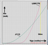
Isn`t the curve seems better? how about J175 or J176?A bit of measured data. The J113 has a lower transconductance "gm" (the slope of the curve).
~
If you are interested in complementary pairs for followers or as CFA
input stages, my preferred parts are the 2SK170, 2SJ74 (or the Linear
Systems equivalents). but the J113 and J176 are good enough for most
of these circuits.
For 10 mA of bias, you would put some resistance between the sources,
typically something in the 22 + 22 ohm range, taking the output off the
center (or maybe use a 50 ohm pot)
The output impedance without degeneration is about 40 ohms, for a
combined gm of about 25 mA/v, about half that of the Toshiba/LS
parts. For the F5 they result in about 6 dB less open loop gain, not
a problem.
The random noise floor for a pair of these is about 1.4 nV (per square
root Hz), compared to about 0.5 nV for the Toshiba parts, which is nearly
a 10 dB difference. A problem when your signal is 10 uV - not so much
when it's 1 volt.
Distortion driving a 10K load at 1V is about 0.015% thd, mostly 2nd
harmonic due to gain mismatch, which can be nulled out or ignored.
In short, these are workable parts.
Nelson how much is the THD with 10k load at 1V for toshiba/LS parts.If you are interested in complementary pairs for followers or as CFA
input stages, my preferred parts are the 2SK170, 2SJ74 (or the Linear
Systems equivalents). but the J113 and J176 are good enough for most
of these circuits.
For 10 mA of bias, you would put some resistance between the sources,
typically something in the 22 + 22 ohm range, taking the output off the
center (or maybe use a 50 ohm pot)
The output impedance without degeneration is about 40 ohms, for a
combined gm of about 25 mA/v, about half that of the Toshiba/LS
parts. For the F5 they result in about 6 dB less open loop gain, not
a problem.
The random noise floor for a pair of these is about 1.4 nV (per square
root Hz), compared to about 0.5 nV for the Toshiba parts, which is nearly
a 10 dB difference. A problem when your signal is 10 uV - not so much
when it's 1 volt.
Distortion driving a 10K load at 1V is about 0.015% thd, mostly 2nd
harmonic due to gain mismatch, which can be nulled out or ignored.
In short, these are workable parts.
Regarding the biasing the Jfets / setting up the constant current source? How much current in general do you recommend? Somewhere on the burning amp festival you were mentioning about the bias in the order of 10ma.
Please clarify me regarding the min and max value of Idss on the Jfets in the datasheet so here minimum means is it the max value possible for the selected jfet from the bunch?
Example: For J175 the Idss is min : -7ma and max -60ma so what does this actually mean? Does it mean that we get maximum value of Idss -7ma in any of these and the Idss might go up to -60ma?
.........so what does this actually mean?........
in most cases means that spoons are made in various sizes , each size is having own name ....... but even if classified in several sizes each of them is having some physical tolerances


Thank you very much Nelson it helped a lot just had few doubts.If you are interested in complementary pairs for followers or as CFA
input stages, my preferred parts are the 2SK170, 2SJ74 (or the Linear
Systems equivalents). but the J113 and J176 are good enough for most
of these circuits.
For 10 mA of bias, you would put some resistance between the sources,
typically something in the 22 + 22 ohm range, taking the output off the
center (or maybe use a 50 ohm pot)
The output impedance without degeneration is about 40 ohms, for a
combined gm of about 25 mA/v, about half that of the Toshiba/LS
parts. For the F5 they result in about 6 dB less open loop gain, not
a problem.
The random noise floor for a pair of these is about 1.4 nV (per square
root Hz), compared to about 0.5 nV for the Toshiba parts, which is nearly
a 10 dB difference. A problem when your signal is 10 uV - not so much
when it's 1 volt.
Distortion driving a 10K load at 1V is about 0.015% thd, mostly 2nd
harmonic due to gain mismatch, which can be nulled out or ignored.
In short, these are workable parts.
Nelson how much is the THD with 10k load at 1V for toshiba/LS parts.
Regarding the biasing the Jfets / setting up the constant current source? How much current in general do you recommend? Somewhere on the burning amp festival you were mentioning about the bias in the order of 10ma.
Please clarify me regarding the min and max value of Idss on the Jfets in the datasheet so here minimum means is it the max value possible for the selected jfet from the bunch?
Example: For J175 the Idss is min : -7ma and max -60ma so what does this actually mean? Does it mean that we get maximum value of Idss -7ma in any of these and the Idss might go up to -60ma?
So many questions.
If you simply match Idss the Toshibas/LS you can get .00X numbers,
and with enough testing you can hit .000X. The J176/J113 parts do
not go this low.
10 mA is a nominal number for bias. With the push-pull circuits the
performance is not heavily dependent on this, so a figure like this
works generally. You can go higher or lower as you like, within the
constraints of dissipation on the parts.
You note that I used the J176, which has a lower Idss than the J175.
My J175 parts come in around 30 mA and the J176 around 15 mA Idss.
Your results will vary, but you get the idea.

Getting matches for these [J113s and J175s] is not easy
If you simply match the Idss of Toshibas/LinearSystems parts you can get .00X distortion numbers,
and with enough testing you can hit .000X.
Since J113 and J175 cost twenty times less money than the Toshiba 2SK170 and 2SJ74, very enthusiastic DIY builders might purchase twenty times as many of them. Drawing candidate devices from a MUCH larger population, the probability of finding a very close match becomes high.
Extremely enthusiastic DIY builders might go one step further, and hunt for matched quads (2xNch + 2xPch). Connecting the two Ns in parallel, and also connecting the two Ps in parallel, gives a good approximation of matched Toshiba devices, at very low cost. And you can buy the parts today, from Mouser and the other usual suspects.
Mark, for this design, within reason of course, wouldn't one be more concerned with the paralleled performance of each complement? A little imbalance between the respective transistors should be quite acceptable if the n and p blocks match.
This relaxes matching requirements handsomely. And nothing to say one couldn't go with even a couple more per polarity, especially with some adjustment of resistors in r1 r2.
This relaxes matching requirements handsomely. And nothing to say one couldn't go with even a couple more per polarity, especially with some adjustment of resistors in r1 r2.
Last edited:
Yes there are more degrees of freedom ("N" number of transistors) than constraints, making it less difficult to find a satisfactory set of devices. I imagine the constraints are probably:
Some people might even jettison number (1.) since it's mostly about getting the same power dissipation and the same junction temperature in all the FETs. If you don't care about matched power, or if power is small enough to be neglected, then maybe (1.) is unnecessary.
- In the final circuit including all resistors, the drain currents should be within X% of each other
- In the final circuit including all resistors, the puller_upper_gm should be within Y% of the puller_downer_gm
- In the final circuit including all resistors, the output voltage offset should be less than Z millivolts
Having gone through this exercise previously, I found that the P's and
N's of the Fairchilds are not similar enough to easily give really low
distortion as complementary parts. If you don't mind a little 2nd harmonic,
then you're OK.
You can tweak around with them to reduce that 2nd, but it's pretty tedious
and cumbersome. The Toshiba/LS parts were designed as complements
for amplifiers, and so they perform better without extra effort.
- Home
- Amplifiers
- Pass Labs
- how about using J111 J175 Jfets in F5