Hello
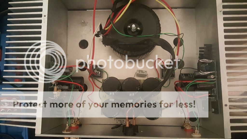
I am wondering if anyone can help me fix this amp. I have a limited understanding but it seems pretty simple. I understand the transformer, then there is what I think is a PSU with various caps and then the Amplifier circuit. The black resistors on the top are smoking when it's switched on. Someone has replaced one channel at one point with different resistors which seems to work ok. I have replaced 3 resistors also but still got the same issue. I would like to put it in a better chasis and perhaps improve some parts if needed. Boards and that sort of thing are available cheaply from China and it would seem better to buy something than spend money on finding the problem as that is expensive. Thats if I knew what to buy. I tried to post some pics but couldn't so i made a short video. Thanks for any help.
Heres the video link.
YouTube
Attachments
This is not a Nelson Pass F3, it's a Tim Rawson rip off.
First Watt Clone f3 by Tim Rawson - Audio Asylum Trader
No wonder it's not working.
First Watt Clone f3 by Tim Rawson - Audio Asylum Trader
No wonder it's not working.
Pretty sure Tim based his work on the design that was made available to the DIY community by Nelson Pass and it does look just like that one so I'm thinking that's it.
Do you know the circuit diagram or is the one in the above post accurate.
Perhaps just to clarify because I think your onto something.
If its a Tim Rawson rip off that suggests its a copy of a Nelson Pass F3 which means it is an F3 build by Tim. If it's not an F3 and it's a Tim Rawson rip off, then that means its a Tim Rawson's own design which means I won't find the circuit in the Pass F3 arena. Would you know which of those is accurate? I'm sure it's the first in which case it is an F3. Thanks
Looks like Peter Daniel's F3 board. For example, see here:
F3 PCB + Lovotech 1016
There were a number of group buys for this pcb so you should be able to find out more.
You can also download the f3 schematics and visually check how well it matches your pcb.
Should also add that if it is a Peter Daniel pcb is should be very close to the published schematics, but
with some minor changes like removing the led and maybe adding some bypass cap.
Last edited:
As far as I know, F3 and ZV9 almost the same.
http://www.diyaudio.com/forums/pass-labs/219893-f3-pcb.html#post3269055
http://www.diyaudio.com/forums/pass-labs/219893-f3-pcb.html#post3269055
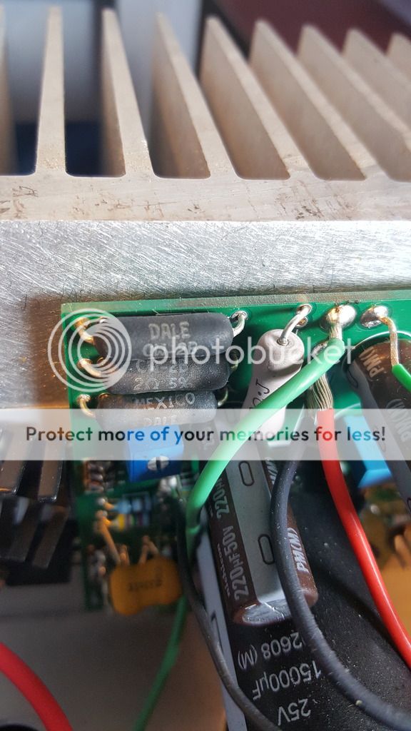
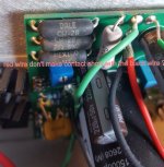
In this picture you can see a previous repair on the left by a technician which seems to work ok. I'm not sure if he did anything else or if it changes the sound. On the right you can see I have replaced them with three new ones but the problem is still there.
Maybe your components on right side board make electrical short contact with the heat sink ? Blue square trimmer around run hot resistors viper position is ~ similar to trimmer on the left side ? Transistors N and P channel is in correct position if compare with the other working board ?
Greetings
")
- Status
- This old topic is closed. If you want to reopen this topic, contact a moderator using the "Report Post" button.
- Home
- Amplifiers
- Pass Labs
- Nelson Pass F3 amplifier help wanted