Is it possible to reduce the supply voltage of ZEN V9, eventually remove the cascoding to obtain a low power (1-2W) good sounding class A JFET amp?
I need it to drive medium/tweeter compression driver with 120dB sensitivity (600hz to 20Khz) 16ohm, so only 1 or 2 high quality low distortion and low noise watt are needed
I need it to drive medium/tweeter compression driver with 120dB sensitivity (600hz to 20Khz) 16ohm, so only 1 or 2 high quality low distortion and low noise watt are needed
Last edited:
You could but having gain on the upper current source is overkill and might even lower performance as you have a 16 ohm speaker. I'd just build the F2 but reduce bias current. If you want more efficiency I'd swap the topmost CCS with say a Hammond 193T which works great in my tweetamps.
My headphone amp right now a F2-cloneish but with C2M1000170D. Nice and low gain on that device.
My headphone amp right now a F2-cloneish but with C2M1000170D. Nice and low gain on that device.
Interesting. Do you have more information and/or a schematic?My headphone amp right now a F2-cloneish but with C2M1000170D. Nice and low gain on that device.
/U.
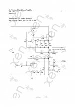
In comparison to e.g. a ZV8, the Zen Version 9 is characterised by :
Cascoded LU1014 triode cell
Aleph dynamic current source
Phase inverting with NFB
Single supply rail
Output capacitor coupled
IMHO, to call it a ZV9 Headamp, a circuit has to retain those characters.
The attached is simulated and not built (and no plan to do so in foreseeable future).
But it gives you an idea, especially the LU1014 triode cell at 300mA with the IRFP cascode.
Performance is decent, but it is a ZV9 variant.
i.e. best driven by a low impedance source, and cannot do away with an output cap.
Whether this is the right solution for your compression driver is another discussion.
Patrick
.
Attachments
Interesting. Do you have more information and/or a schematic?
/U.
I can do that:
My goal was to have a current source headphone amp to got that nice distortion reduction. My headphones are AKG K712 phones which have pretty flat impedance curve so they perform well with a current source amp without fiddling with EQ. I do have a DSP unit I was prepared to use to fix the response with the amp but found that I didn't need it.
The output resistor is not really needed but it lowers the on/off thump to almost nothing and reduces the gain a bit more.
It is powered by a 24V smps.
Attachments
thanks all for your replies and sujestions
indeed I should have called tweeteramp instead of headamp and maybe neither zen V9...
cap coupled output is fine for me, I will anyway put a MKT 40mF cap in series with the compression tweeter to protect it.
is there a bias point where the LU1014 can work as a triode without the cascoding ? I know that the cascoding modulation reduces further distortion, but I would keep the circuit as simple as possible.
Whether this is the right solution for your compression driver is another discussion.
Patrick
.
Do you have any other simple and good sounding alternative for my compression drivers? (JBL2446)
Schematics only.
Patrick
.
How does it compare to the your DAO SE ?
I can do that:
My goal was to have a current source headphone amp to got that nice distortion reduction. My headphones are AKG K712 phones which have pretty flat impedance curve so they perform well with a current source amp without fiddling with EQ. I do have a DSP unit I was prepared to use to fix the response with the amp but found that I didn't need it.
The output resistor is not really needed but it lowers the on/off thump to almost nothing and reduces the gain a bit more.
It is powered by a 24V smps.
I was interested in this amp and I would like to try this modification and Patrick schematic.
I've done some simulations with the OllBoll scheme but I can´t get them to work properly.
If there is no problem, I want to do some boards only for my private use and perform some tests.
I have this ready. I can adjust BIAs correctly at 12.80Vdc (B+25.6Vdc). It´s very stable. Until here, all OK but I have a problem with the offset. It´s around 12Vdc. (I measure it between - out and B+)
If I remove the electrolytic C3 (220uF/35v), the offset is close to 0V (only 1uF on C2). What value do you recommend for C3 capacitor? Maybe I'm forgetting something.
If I remove the electrolytic C3 (220uF/35v), the offset is close to 0V (only 1uF on C2). What value do you recommend for C3 capacitor? Maybe I'm forgetting something.
...I have a problem with the offset. It´s around 12Vdc. (I measure it between - out and B+) ... If I remove the electrolytic C3 (220uF/35v), the offset is close to 0V.....
As ZenMod says: a cap-coupled output "MUST" have a resistor to ground, or else it will show some offset.
The 220uFd electrolytic has maybe 0.2mA leakage. On nearly any volt-meter this will bring the output to essentially your 12.8V on the other side. The 2uFd film has less leakage and with many voltmeters will show low offset, but also poor bass response into a typical load.
As ZM says, measure with anything like 300 Ohms connected (though not your headphones in case there's some other problem!). If the electrolytic has full 0.2mA leakage you will (after a few seconds charge-up) see 0.060V (60mV) which is fine. Actually good-quality electros have lower leakage and declining with time, so 10mV may be typical.
Thank you so much guys.
I understand that I must put a resistance of bleeding after the capacitors but with this design I´m a bit lost when using the negative output and B + as common.
In the original design of the F2J there are 3x 47r in parallel (around 15r in total) to ground but here I only have to put the resistance recommended by Zen to B +. I'm wrong?
Why is not a bleeding resistance used between -out and B + in the original design?
I am using Nichicon KW and UKA (220uF, 470uF, 1000uF and 2200uF).

where you're connecting headphones , between output (called -out) and ?
I'm sorry, I was distracted re-reading some threads about F2.
My first think was use ground like a common but then I think in positive rail
Last edited:
- Status
- This old topic is closed. If you want to reopen this topic, contact a moderator using the "Report Post" button.
- Home
- Amplifiers
- Pass Labs
- modify Pass Zen V9 as Headphone amp?