Too bad on the caps misorder (or fulfillment). Easy to do, I bet. I spent some time today reviewing my pending order with Digi-Key. Pleased at how many part numbers are unchanged after 20 years, but still had to substitute the “obsolete” items. Still not sure I’ve picked the right diode bridge. And I’m really perplexed with the optional potentiometers. I like the idea of the added flexibility, but not a clue how to handle the four potentiometers that aren’t on the PCBs. Still, Great of Nelson to mention the basic standard voltages in his article so we’ve got something to go on.
I take it you went with the Y23 range of transformers? The manufacturer told me the D4007s would be at least $100 each if I wanted them as specced.
Good luck.
Jim
I take it you went with the Y23 range of transformers? The manufacturer told me the D4007s would be at least $100 each if I wanted them as specced.
Good luck.
Jim
Yes, I bought the Y23 transformers direct from Avel, they were $23 a piece. I'm using four ganged 24 step pots for the volume and gain control, had to order the 5K version. P5 is where I'm unsure, from the comments in the projects section of Pass DIY, one solution I liked was a switch to change overall gain using fixed resistors. I have plenty of time to decide as I'm waiting on an enclosure and the 5K pot.
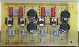
I'm using rectifier bridge (digi-key P/N KBP202GDI-ND) which is 200V 2A, fits perfectly on the board. P1&2 will be mounted on the front panel as the Volume control. I'm using a quad (4) ganged 24 step 10K pot (it uses Vishay Dale resistors). P3& 4 is another quad (4) ganged 24 step 5K pot (it also uses Vishay Dale resistors) which I will either mount on the front panel OR the rear panel as a "gain" control. N. Pass in the article for the Balanced Zen line stage describes it a Gain Control which can also be used for Volume control. I don't understand how that works, I'm thinking it is something I may adjust sometimes.
P5 is also for gain of the MOSFETS, once again I'm not real clear on this. I always thought preamps were for input selection, volume control, balance control, tone control etc. I wasn't aware there is any gain/amplification of the input signal except for phono sections.
I have to reread the articles and comments of others who have built this to see about P5, somewhere I remember reading about a fixed resistor of 532 ohms. Not sure if my memory is correct, which is why I need to reread Nelson's article and all of the comments on PASS DIY and anywhere else I can find.
I have the line stage board built and soldered, I'm waiting for an enclosure and the 5K quad ganged pot from China to arrive, so I have time to read up before I make any decisions.
...make your own (15 years a go!)
if i could do it, anyone can!
Good morning moe29,
Do you happen to have Gerber or cad files for the boards you made?
The original article says they can be found at passdiy.com but I can't find them.
Thanks,
-BB
...make your own (15 years a go!)
if i could do it, anyone can!
I notice you didn't install P5. what did you do regarding gain adjustment if anything?
Jim
Good morning moe29,
Do you happen to have Gerber or cad files for the boards you made?
The original article says they can be found at passdiy.com but I can't find them.
Thanks,
-BB
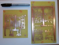
I used a Laser Printer on to PCB Circuit Board Thermal Transfer Paper.
Just use the art from the BZLS article. I scanned it and did touch ups in Photoshop.
Then print it on to the special paper and iron it on to your coopper
clad board and etch away
")
i found it fun to make my own boards - they don't look as professional,
but they work just as well for these 1 sided boards.
(there's peeps that can get very professional looking results with these
methods, adding the silk screen info, etc.)
give it a try! you won't have to sit around waiting for your order to show up
in the mail. And it's nice to know how to do for future projects.
Last edited:
I notice you didn't install P5. what did you do regarding gain adjustment if anything?
Jim
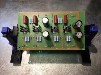
I hooked up P5 when the boards were installed. Running wires from the front
panel to the unpopulated holes seen in the pic.
The BZLS is a VERY adjustable preamp! You can attenuate the Input signal with P1 and P2.
You can attenuate the Output signal with P3 and P4. And "P5 allows
intrinsic adjustment of the circuit gain without having to match the potentiometer
values, allowing adjustment from 10 t0 20 dB gain."
To this day i think the BZLS is Nelson's masterpiece DIY article. Just an amazing
piece of kit that holds it's own today. At least that's how i feel
I used a Laser Printer on to PCB Circuit Board Thermal Transfer Paper.
Just use the art from the BZLS article. I scanned it and did touch ups in Photoshop.
Then print it on to the special paper and iron it on to your coopper
clad board and etch away
i found it fun to make my own boards - they don't look as professional,
but they work just as well for these 1 sided boards.
(there's peeps that can get very professional looking results with these
methods, adding the silk screen info, etc.)
give it a try! you won't have to sit around waiting for your order to show up
in the mail. And it's nice to know how to do for future projects.
Thanks,
I have been making my own boards for a long time using toner transfer method and 3:1 H2O2 : HCL for etching.
I have not tried printing from existing artwork I have always designed my boards using Eagle.
No reason I can't copy, save, and print the .PNG images directly from Mr. Pass's article.
Thanks for the thought.
And yes making your own PCB's is fun, fast, and rewarding!
-BB
bbm3 - The Gerber files are located in post #36 on page 4. Nelson Pass posted them.
elwood625,
Thank you very much!
-BB
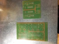
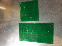
Here are photos of the PC boards I had made from N. PASS's Gerber files he sent me. Also, a photo of the completed Line Stage Board, note that P5 is missing from each channel as I have yet to decide the value of the fixed resistor I'm going to use.
In his article, NP says:
" If you elect to use P1-5 to adjust the parameters of the circuit, you can gain quite a bit of flexibility in its use. In general, the best performance occurs with the higher value of P5, giving 10 dB gain instead of 20 dB. If you don't need the gain, use 10 dB."
I'd agree say 10db is plenty for me. P5 in the BOM is specced at 500 Ohm. Can we just drop in something close to that? I am waaaay over my head when it comes to substitutions.
Just buy them from elwood625. I did. They look good and I don't see how you could do it any cheaper.
For me making my own PCB's is a big part of DIY.
-BB
From what I read on page 7 of BZLS article, "In general, the best performance occurs when the higher value of P5, giving 10dB of gain instead of 20dB." On page 8, "Figure 10 shows the performance with R15 at 430 Ohms, for a gain of 10dB."
With the BOM showing R15 at 124 ohms, P5 would then be 306 ohms. Better yet, replace R15 at 124 ohms, with a resistance of 430 to 500 ohms and P5 is a jumper wire.
I was going to find something I have in stock close to 430 ohms, since he referenced that value in a measurement test showing best performance.
- Status
- This old topic is closed. If you want to reopen this topic, contact a moderator using the "Report Post" button.
- Home
- Amplifiers
- Pass Labs
- Which preamp for Amp Camp?