I think #5 is particularly cute.
Thanks, sir. That's my favorite as well.
")
I think I'll queue that one up first.
My apology gior as I am mistaken in my above post. The Vds polarity for 2SJ28 as shown in your schematic is correct. The grounded source of 2SJ28 is positive relative to its drain. The polarity of V [colector-emitter] for PNP is also correct. The Vds for P-Mosfets is also proper. The top right part of the amp schematic shows a negative power rail relative to ground.
Hi Antoniel, thanks you for having gone through it a second time and for confirming schematic is ok.


I played a little with the current output DEF amp from Antoinels post (#80).
This is not the recommended bias-method. I just wanted to test the amp without any global feedback in LTSpice.
A very nice pushpull current-out amp. The voltage output asymmetry is a very classical second harmonic SIT or triode character.
I guess it would sound very good, despite the simulated 1.47% THD.
Thanks for a great idea Antoinel!
Cheers,
Johannes
I don´t mean to bash the 2SJ28, but I don´t understand why one would like to use one to drive loudspeakers.
Even though I don´t like the lack of transconductance, I believe the 2SJ28 is nice sounding and quite linear device (under the right conditions).

With a few UJN1208K SIC Jfets and a nice triody IRF3711 we can use the 2SJ28 for the input Jfet/SIT in something distantly resembling a FW J2 but with a low impedance feedback-node.
The cascoded IRF3711 and UJN1208K is meant to be similar to the Zen v.9 in the inherent distortion-reducing mechanism, by playing with the sweet-spot of a triode character and cascode-modulation.
Cheers,
Johannes
Hello, Mr. Rothacher. Please consider the attached schematic as a viable idea for using bachelor/ette 2SJ28.
Thanks, Antoinel. Have you identified a candidate for the NMOS?
Tks Mr. MR!
Could you help me the value of that resistors, trims and bias in schm (6)!
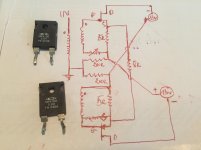
#6: The rheostats would be say, 4 ohm, 25W types. The resistors from output to ground, let's say 200 ohms, the floating supplies 13-22V. You want to first match your VFETs as closely as you can then use the rheostats to dial up the correct current and balance for low output offset. There may be a trick or two to try as well, and we can touch on that when I get into #5.
Thanks, Antoinel. Have you identified a candidate for the NMOS?
Hello Mr. Rothacher. The NMOs is IRFP140N. In the event this idea does not bubble up, I already have the resultant prototype on the bench playing music. Here are its details:
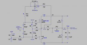
1. It is a modification of the DEF prototype [2SJ28 + IRFP140N] which I reported earlier in post#126 in the Thread DEF initiated by Mr. Pass.
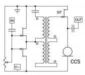
2. The left schematics in this post is the identical above prototype DEF plus a modification which appears to the right of the FETs. The FETs now operate in the common source configuration [opposed drains] to give both voltage gain [8 Vin], and power gain. DECS is a current source amp unlike its parent DEF which is a voltage source amp.
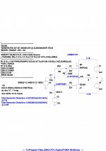
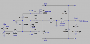
The right schematic is complete for the prototype understudy. Note the following 3 details.
1. A Zobel [10 Ohm +0.1uF] was needed at its output to get rid of a sustained spontaneaous oscillation.
2. A DC servo to lower the DC offset at Vout down to <50 mV.
3. The resistors labeled * were added/used so as to render the level of Vin equal at both gates of the FETs and to allow the gates of the FETs to see Vout ~equally for positive feedback.
The objective for DECS is to use it without a line level amplifier and to drive loudspeakers which accept a current source amp. DECS is driven directly by a CD player's headphone output. DECS's output drives two full range 15" raw drivers [called musical instuments by MCM] which are connected in parallel [4 Ohms net]. The system's music is full bodied [rich bass] and has the clear and detailed highs I've already noticed from that of its parent DEF.
Attachments
Thank for you help!#6: The rheostats would be say, 4 ohm, 25W types. The resistors from output to ground, let's say 200 ohms, the floating supplies 13-22V. You want to first match your VFETs as closely as you can then use the rheostats to dial up the correct current and balance for low output offset. There may be a trick or two to try as well, and we can touch on that when I get into #5.
We stored some good matched 2sj28 just before they out of stock, Thanks N.Pass and Nagini a lot
If you don't mind, I have some good 5r in hand and want to use them but I don't know if it work or not or V supplies or Vsg of 2sj28( my matched pair2sj28 have Vgs from 4.8 - 12.5v) are argreeable.
Best Regards
Jamahamvui.
Attachments
Are you saying that one of your 2SJ28's has a Vgs of 4.8V and the other has 12.5V (for what current?) Or, are you saying you have a matched pair with Vgs 4.8V (again for what current)
In this project, you want the lowest Vgs values possible, since we're using self-bias. You also want adjustable resistance, which is why I used rheostats. 4.8V won't leave much across your SITs, so you'll be wanting to use higher supply voltages.
In this project, you want the lowest Vgs values possible, since we're using self-bias. You also want adjustable resistance, which is why I used rheostats. 4.8V won't leave much across your SITs, so you'll be wanting to use higher supply voltages.
http://blog.audiomaker.tech/pdf/sixeasypieces.pdf
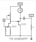
http://blog.audiomaker.tech/pdf/soundhappy.pdf
6 + 1 = name " 7 Marvelous of The Vfets "
What are you Going to do with That? Perspectives on Life After a Degree in Physics: Nelson Pass, Audio Amplifier Designer, Founder of Pass Labs and DIY Audio
What about KF-33 if compare to KE-33 2SJ28 ?
http://blog.audiomaker.tech/pdf/soundhappy.pdf
6 + 1 = name " 7 Marvelous of The Vfets "
What are you Going to do with That? Perspectives on Life After a Degree in Physics: Nelson Pass, Audio Amplifier Designer, Founder of Pass Labs and DIY Audio
What about KF-33 if compare to KE-33 2SJ28 ?
Attachments
I am currently listening to this:
Steely-eyed missile man
Are you playing it with the Tannoys? I should start looking around for some of those drivers.

I am currently listening to this:
Nice. Just the right number of parts. Low that is.
- Status
- This old topic is closed. If you want to reopen this topic, contact a moderator using the "Report Post" button.
- Home
- Amplifiers
- Pass Labs
- What To Do With Those 2SJ28's