Finally completed VFET Amp
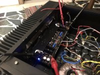
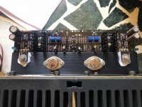
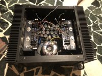
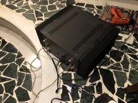
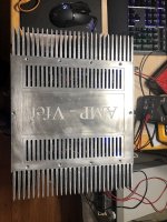
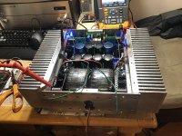
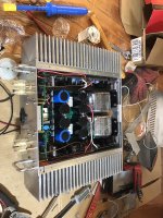
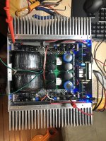
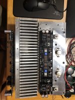
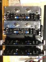
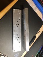
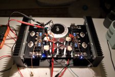
6L6, thanks for your VFET build guide. After having bought the VFET kit from DIYAUDIO store more than 3 years back, I finally found time to complete the amp. Thanks to the build guide, putting together this amp was a breeze. I managed to setup the VFET bias to 1.5 amps due to big Heatsink’s I had. The amp works wonderfully. The best sound I heard so far. Standout quality is the timbre of voices and instruments.
Thanks Papa for a brilliant design.
I am not fugly in build looks, but quite functional and does the job well. Here are some pictures.
Cheers.
Anil
Attachments

Uneven gain between 2 channels
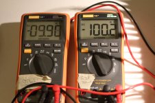
I have been playing the VFET amp for the last 2 days after the build. I noticed that one of the channels has lower gain than the other one. Is it possible? What should I look at ? Both the channels are biased at the front end and at the VFET similarly.
I will recheck the bias levels once again. There seems to be atleast 3dB difference between the two channels. One Channel has VFETs marking of 81 and 89 and the other channel has 81 and 94 for vgs measurement. Could this be the issue?
Regards
Anil
The markings and bias should not have the effect you noted.
Did you make measurements? Trying switching inputs, etc?
Also have a look if R3/R4 values are correct.
Thanks. The problem seems to be from the vintage yamaha preamp, which has a sticky volume control.
Regards
Anil
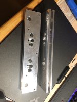
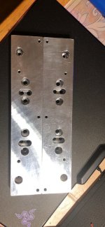
My Vfet Amp
I am gradually completing my vfet amp project after 3 long years
there are a few small changes, instead of using the T heat sink I made into the U heatsink, helping the PCB parallel to the heat sink, saving maximum space inside the chassis
Chassis size now: outside 400 x 320 x 120, inside 235 x 300 x 115, compact for a class A amplifier, I like that
I am having a small problem with my amp, and need your comments and help:
currently i am using 2 separate sources for 2 channels of amp, I have yet to match the mass scores of the 2 channels with the overall mass points of the chassis,
2 channels that work individually are perfect
but I can't bring them to the overall mass point of the chassis, because between the 2 points of the 2 channels mass appear voltage of 12.3 AC, My scopemeter died a B channel when I accidentally created a common point between the two amp channels, I don't know why?
,Why Why Why??? I have checked the rectifier diodes, there is no AC voltage detection between them, the DC sources are clean sources. Can someone help me, tell me what should I check?
and I am designing the front of the chassis, can someone give me an idea?
Attachments
-
 49730951203_c58bd17030_c (1).jpg162.8 KB · Views: 187
 -
 49731725787_5ea82e7895_c.jpg154.6 KB · Views: 174
 -
 49730856208_800c9108c1_c.jpg184.9 KB · Views: 172
 -
 49731723682_95660d88d5_c.jpg192.6 KB · Views: 190
 -
 49731725717_140690c937_c.jpg174.5 KB · Views: 191
 -
 49730854023_6d9ae18395_c.jpg164.2 KB · Views: 196
 -
 49731725747_ce7152ae47_c.jpg139 KB · Views: 134
 -
 49731723997_a4f0e8ecbd_c.jpg87 KB · Views: 150
 -
 49731402266_555184e59d_c.jpg138.7 KB · Views: 379
My Vfet Amp
The problem was solved, because I used the same source for the speaker protection.
I am designing the front of the chassis, can someone give me an idea?
thank everyone !
The problem was solved, because I used the same source for the speaker protection.
I am designing the front of the chassis, can someone give me an idea?
thank everyone !
Attachments
Started back working on my VFet amplifiers (monoblocks) I was chugging along there awhile back, and up to the point of doing adjustments, when I figured out that I had PSU issues. First, I had the wrong transformer voltage (too many different VFets out there, and I picked wrong, not terribly. I also, at that time, could not get the DIYAudioStore power supply boards, as they were out there for awhile. I used a set of PSU boards from ebay, and one of them shorted out right off.
I did start with the full VFET kit from the store, including store matched input transistors.
I took some time off, putting my Aleph J back in service, and subsequently I am using McIntosh MC60 amps, that my dad had in the attic, and getting them reconditioned.
With the enforced home time due to Covid-19, I decided to give them another shot, and got new Antek transformers, and new PSU boards from the DIYStore. I put all that back together on the first monoblock. PSU voltage now 28 as per spec. After an initial setting of values for 1.2v, 1.2v, 100mv, and 0.4mv offset, I tried some rather non-sensitive speakers, and got a bit of sound out. I let it run for a bit more, re-did the values to the above numbers, but when I hooked the speakers back up no sound at all out of the amp. The transistors are all warm, not hot, all the LEDs are lit, and the settings are staying stable. No magic smoke, no pops, no scorched components.
I'm not sure I have the enthusiasm to update the PSU+transformer in the other box at this point.
Where should I even look?
Started back working on my VFet amplifiers (monoblocks) I was chugging along there awhile back, and up to the point of doing adjustments, when I figured out that I had PSU issues. First, I had the wrong transformer voltage (too many different VFets out there, and I picked wrong, not terribly. I also, at that time, could not get the DIYAudioStore power supply boards, as they were out there for awhile. I used a set of PSU boards from ebay, and one of them shorted out right off.
I did start with the full VFET kit from the store, including store matched input transistors.
I took some time off, putting my Aleph J back in service, and subsequently I am using McIntosh MC60 amps, that my dad had in the attic, and getting them reconditioned.
With the enforced home time due to Covid-19, I decided to give them another shot, and got new Antek transformers, and new PSU boards from the DIYStore. I put all that back together on the first monoblock. PSU voltage now 28 as per spec. After an initial setting of values for 1.2v, 1.2v, 100mv, and 0.4mv offset, I tried some rather non-sensitive speakers, and got a bit of sound out. I let it run for a bit more, re-did the values to the above numbers, but when I hooked the speakers back up no sound at all out of the amp. The transistors are all warm, not hot, all the LEDs are lit, and the settings are staying stable. No magic smoke, no pops, no scorched components.
I'm not sure I have the enthusiasm to update the PSU+transformer in the other box at this point.
Where should I even look?
Post detailed pictures please.
Might be something over looked. Like input wires crossed.
Rush
An externally hosted image should be here but it was not working when we last tested it.
An externally hosted image should be here but it was not working when we last tested it.
An externally hosted image should be here but it was not working when we last tested it.
An externally hosted image should be here but it was not working when we last tested it.
An externally hosted image should be here but it was not working when we last tested it.
Need to right click and open in new tab
Last edited:
Daft question. I am replacing a nicely working Aleph J with this build from the DIYAudio kit. In terms of the PSU, which is the standard PSU with regulator boards intact, can I simply replace my toroid for the Aleph J with the (2x 22Vac secondaries) one for the VFet? Or do I need to replace R1-8 with different values?
PSU is the DIYAudio one.
PSU is the DIYAudio one.
Assuming your R1-R8 are 0R47 each, you'll be looking at something like 0R1 (four 0R47 in parallel) per polarity in your CRC PSU, which is perfect. See post #1 for reference.
You must however make absolutely sure that your PSU capacitors are rated for the higher supply voltage! That means caps rated for 35VDC or higher.
You must however make absolutely sure that your PSU capacitors are rated for the higher supply voltage! That means caps rated for 35VDC or higher.
Pass DIY Addict
Joined 2000
Paid Member
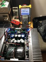
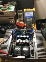
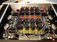
Several years later and I finally found time to finish my VFet2 build. The boards have been stuffed for quite some time and I just picked up a chassis for it. It's a Dissipante 3U and sees a temp rise of about 23-24c.
The T-bar and heat sink needed a bit of work to mate better, so I used some valve lapping compound the scrubbed the two together for about 30-40 minutes to close the gaps. The transistors are mounted with ceramic oxide insulators and heat sink paste. I used a 400VA Antek transformer with TeaBag's CRC boards populated with 4 x 39kuF and 3 x 0R22 3w per rail.
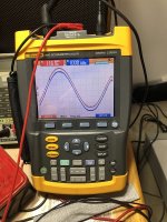
After running for about 90 mins, I dialed in bias at 100mV and managed to reduce offset to about 10mV (at least for now). Those single-turn pots are a bit twitchy as others have pointed out, but with some patience it all works out.
Best of all - it makes music Only played with test speakers so far, need to finish up the chassis. Many thanks to Nelson for sharing such a great design and parting with so many vintage transistors and to 6L6 for the build guide!
Now I just need to find a place to put it. I think this is my 12th amp after hanging around here all of these years. My wife swears it's a sickness I still have bagged parts for another few amp projects...
The T-bar and heat sink needed a bit of work to mate better, so I used some valve lapping compound the scrubbed the two together for about 30-40 minutes to close the gaps. The transistors are mounted with ceramic oxide insulators and heat sink paste. I used a 400VA Antek transformer with TeaBag's CRC boards populated with 4 x 39kuF and 3 x 0R22 3w per rail.
After running for about 90 mins, I dialed in bias at 100mV and managed to reduce offset to about 10mV (at least for now). Those single-turn pots are a bit twitchy as others have pointed out, but with some patience it all works out.
Best of all - it makes music
Only played with test speakers so far, need to finish up the chassis. Many thanks to Nelson for sharing such a great design and parting with so many vintage transistors and to 6L6 for the build guide!Now I just need to find a place to put it. I think this is my 12th amp after hanging around here all of these years. My wife swears it's a sickness
I still have bagged parts for another few amp projects...Attachments
Last edited:
Several years later and I finally found time to finish my VFet2 build. The boards have been stuffed for quite some time and I just picked up a chassis for it. It's a Dissipante 3U and sees a temp rise of about 23-24c.
The T-bar and heat sink needed a bit of work to mate better, so I used some valve lapping compound the scrubbed the two together for about 30-40 minutes to close the gaps. The transistors are mounted with ceramic oxide insulators and heat sink paste. I used a 400VA Antek transformer with TeaBag's CRC boards populated with 4 x 39kuF and 3 x 0R22 3w per rail.
After running for about 90 mins, I dialed in bias at 100mV and managed to reduce offset to about 10mV (at least for now). Those single-turn pots are a bit twitchy as others have pointed out, but with some patience it all works out.
Best of all - it makes music
Now I just need to find a place to put it. I think this is my 12th amp after hanging around here all of these years. My wife swears it's a sickness
Eric,
Great job and that’s some stick-to-it-ness! We will look forward to your listening impressions.
Cheers,
Greg
The T-bar and heat sink needed a bit of work to mate better, so I used some valve lapping compound the scrubbed the two together for about 30-40 minutes to close the gaps.
I also found it was not mating very well... so I added some intermediate screws closer to the middle (one on top side that you can see and 2 on the bottom side) . I find the standard holes a bit too close to the border of the T-bar too. You can see on the picture the light shining between the T-bar and the sink when it was fixed without the additional screws (and without compound). Since the sinks are a bit on the small side, better not to loose too much heat conductivity on the way out ;-)
Very nice build! I like it when it is compact. I have the same case and put the transformer under the capacitors.
It is (currently) my best amp ever and use it daily

Attachments
- Home
- Amplifiers
- Pass Labs
- Sony vFET Illustrated build guide