I have the opportunity to get a Sony ta-5650. The owner says that the light turns on when powering on but it does not give out sound. Beyond opening it up are there any ways to indicate that the VFETS are ok?
Thanks,
Well assuming the fault in the amp is not in the output stage, measuring the bias and dc offset would definitely confirm everything is operating correctly.
Thanks everyone!
Anand, unfortunately I don't have a setup to measure THD, nor the knowhow yet. It's next on my to-do list. The fact that the amps see half the speaker impedance, wouldn't that decrease the damping factor by half?
Sabrosa, I couldn't find any professional place to CNC the faceplates. From the few replies I've received, they seemed to have more orders coming in than what they were able to produce.
I ended up stumbling on a relatively local machinist with a CNC and workshop at home. He was open to produce the faceplates and the top plate cut-outs in-between other projects. From the time I sent him the CAD files, it ended up taking a few months for him to be able to CNC the parts and I had to slightly modify the dimensions to fit standard aluminum plates' thickness and width.
Paul
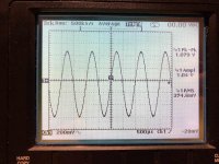
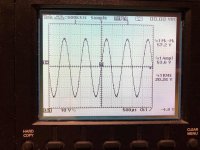
I got around to measuring the bridged Vfet output. I used a 1 KHz tone played from the computer to the network streamer, into the DAC and preamp.
I used an oscilloscope that has isolated channels and a 8.2 ohms measured dummy load.
In order to simulate how much power is output from the Vfet with normal volume, I first set the preamp attenuation to my preferred listening volume. With that setting, I had an RMS voltage of 0.374 mV. If my calculations are correct, that comes out to only about 0.017 W?
I would expect it to be much higher.
When I repeated the same measurements with the preamp attenuation to the minimum (max volume) I had an RMS voltage of 20.26 V, which gives an output of 50 W, without seeing any clipping on the oscilloscope.
Did I mess something up in my measurements or calculations?
Attachments
Well assuming the fault in the amp is not in the output stage, measuring the bias and dc offset would definitely confirm everything is operating correctly.
I received a different 5650, which was in working condition. I opened it up and everything looked clean. I opened it up to check the v-fets and they all ranked 55, but the only thing that seems odd is that there are 3 2SJ18 and 4 2SK60, I attached images of them. So they have not matched pairs, would this make a difference?
Attachments
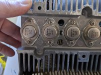
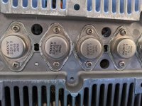
Here's a picture of what they should look like.I received a different 5650, which was in working condition. I opened it up and everything looked clean. I opened it up to check the v-fets and they all ranked 55, but the only thing that seems odd is that there are 3 2SJ18 and 4 2SK60, I attached images of them. So they have not matched pairs, would this make a difference?
I would surmise your unit might be working on single pair per channel. You should not operate it until you have bias checked and unit inspected.

you can expect new Sony VFet kit from Pa and Store , any day keep an eye on it , but don't despair if any day is little longer those funny guys , inventing new things for fun and living - they have different time perception than us , mere mortals
Thanks ZM, I was beginning to lose hope of ever building a SIT amp. I am gathering projects to work on this year after being inspired by my Aleph J build. Just disillusioned that most of the projects use obsolete unobtainium parts.
 At least I have some 2SK170, 2SJ109 and 2SK389s...just missing the elusive 2SJ74.
Appreciate the reply.
Cheers
Here's a picture of what they should look like.
I would surmise your unit might be working on single pair per channel. You should not operate it until you have bias checked and unit inspected.
View attachment 825344
Thanks for the reply!! Sorry for not responding earlier, the school I work at here in Los Angeles, closed abruptly and we've been scrambling to get online learning up and running. Crazy times!
My vfets look like the one's you posted and match with a rating of 55.
It plays well and all the functions work without issue. I know that the diodes are in need of immediate replacement because all the parts are still the original ones. I ordered the right diodes and was going to have a tech install them and check the amp out. Unfortunately, California is on lockdown and the tech is in his 60's so I don't want to risk him getting the virus. So, I am going to replace the diodes myself. I have done a little work on stereos but mostly bulbs and caps, but I am a complete novice otherwise. My main question before beginning is there a certain orientation the diodes need to be in, aka black stripe at the bottom? I know that two diodes need to be joined in series.
Thanks and stay safe!
My buddy is willing to sell me a matched set of these Sony vfet
I know there is few choice
Csx1
Sony vfet this version
Sony vfet new upcomming
Which project should I pick or should I just wait for the new project from papa?
Since I already got the transformer for it 20v x 2.
Which is the most versatile? Say good driving capability?
And where do you get the t brackets... Can't find it anywhere
Thanks in advance

made you own ........
make, sleepy Dodo
I don't believe you.

my lips are sealed .....
Thanks for the reply!! Sorry for not responding earlier, the school I work at here in Los Angeles, closed abruptly and we've been scrambling to get online learning up and running. Crazy times!
My vfets look like the one's you posted and match with a rating of 55.
It plays well and all the functions work without issue. I know that the diodes are in need of immediate replacement because all the parts are still the original ones. I ordered the right diodes and was going to have a tech install them and check the amp out. Unfortunately, California is on lockdown and the tech is in his 60's so I don't want to risk him getting the virus. So, I am going to replace the diodes myself. I have done a little work on stereos but mostly bulbs and caps, but I am a complete novice otherwise. My main question before beginning is there a certain orientation the diodes need to be in, aka black stripe at the bottom? I know that two diodes need to be joined in series.
Thanks and stay safe!
Just Google - repair /restoration of TA -5650, you can see photos showing the orientation and more information - care to be taken - mostly Audiokarma website / also on this forum - plenty to help you
- Home
- Amplifiers
- Pass Labs
- Sony vFET Illustrated build guide