Hi Andrew,
You mentioned that when you tried measuring the vfets, they got really hot.
Do you recall it that was with the ones that had the numerical markings on them?
If those 14.x markings are Vgs values at some non-zero current, it's possible
that this circuit does not give high enough Vgs to keep the current low.
Dennis
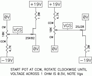
The Vgs measuring circuit calls for 0.5A so there will be heat. Heat sinking is probably best if power is applied for any length of time. The 14.xx markings are probably Vgs values for 0.5A at 19V or 20V. Nelson's test criteria was 0.5A at 20V Sony Vfet Illustrated build guide .
To make sure that you don't run out of voltage for Vgs, reverse the positions of the 10K pot and 4.7K resistor so that the full 19V is available.
To make sure that you don't run out of voltage for Vgs, reverse the positions of the 10K pot and 4.7K resistor so that the full 19V is available.
Ben is right on as usual.
In fact, I would argue the that the switched order is superior since it keeps
the Vgs well away from zero and minimizes the chance of high current.
Andrew, in light of Ben's comment, do you want to try measuring your parts
again (assuming you haven't sent them off to be tested). (Start at 19V at Vgs
and slowly decrease it while monitoring the current (across the 1ohm resistor)
Dennis
Hello,
I’ve sent them now to a friend in California. He’s going to test them with a curve tracer or sum he said. I’ll pass on your advice. I have 3 pairs of 2sj28 and 2 pairs of 2ak82. Some unmarked. The high heat unnerved me so I’d prefer not testing myself.. Probably be another two weeks before I get them back. I’ll let you know.
I’ve sent them now to a friend in California. He’s going to test them with a curve tracer or sum he said. I’ll pass on your advice. I have 3 pairs of 2sj28 and 2 pairs of 2ak82. Some unmarked. The high heat unnerved me so I’d prefer not testing myself.. Probably be another two weeks before I get them back. I’ll let you know.
Turn on transient when warm
To continue from earlier, I lost V- .
I took out the VFETs. Examined the power supply. There was one place where one of the output wires from a diode bridge was loose. I fixed this. Replaced resistors that blew. And ran both polarities for a few hours with an incandescent bulb. This went ok.
I rebiased the front end. One channel at a time. This seemed to go ok.
I installed the VFETs for one channel and initial setup went ok - ran for about half an hour. output DC offset < 40 mV. Voltage at R32 about 90 mv . I had not closed the box yet.
I turned off the amp and within a minute, turned it back on. One of two fuses in the AC input blew. Thinking, this may have been the case in the initial problem that resulted in no V- either : Turn on without a long time off, to cool off. Is there any problem that this points to?
I let the amp cool for ~ 10 minutes and then replaced the fuse and turned it on. It seems to run ok. Voltages at R32 and the output DC offset for the channel with VFETs seem as before.
Please let me know if you see anything amiss in the picture and as always, thanks for the help.
Attachments
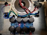
I couldn't tell see much in the picture. A wider angle shot showing wiring to the boards would give more information. You also have tape in many spots obscuring the wiring.
What size fuse are you using? If the fuse is a bit low, rapid off and on may blow the fuse because the CL60 thermistors are still hot and therefore have low resistance, allowing high current flow. The CL60 when cold has high resistance (about 10 ohms if I remember correctly) and that slows the current surge as the capacitors initially charge.
If you are now getting low offset and reasonably correct current through the circuit and voltages are correct, then it is working properly, and it is time to try your other channel.
For proper final setup you will need to put the cover on in between adjustments. With the cover on, the operating temperature will increase and the offset and current will change. So it is best to adjust, put the cover on and run it for some time, and then quicky adjust and put the cover back on. To do this efficiently it is best to have three meters and also clip leads so that you can keep the meters connected while the cover is in place and the amp is heating up. With the meters hooked up you can monitor the readings and decide whether you need to increase or decrease the pots before taking the cover off. It is probably best to do one channel at a time.
When making adjustments, it is best to go half way and then let the amp stabilize, and then make further adjustments, until you slowly reach a point where it is close enough.
As Ben says, the thermistors when hot have a very low resistance and it's not uncommon for the fuses to blow when a short power-off/power-on cycle occurs.
You are more than welcome to bring the amp to my house and we can get it set and running if you find yourself on my side of town...")
You are more than welcome to bring the amp to my house and we can get it set and running if you find yourself on my side of town...
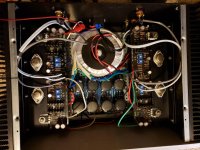
Thanks Ben. Here is another picture. I suppose I went overboard on black tape.
Too kind Jim. It may come to that. I sure do appreciate the offer.
Fuse is 3A fast blow. That is what I got locally. Good point about the CL 60 thermistors. I'll order slow blow ones. Do you think I should step up to 4A or 5A or stay at 3A? The transformer is 400VA.
Yes, I put the whole box together to let it warm up. One channel seems reasonable so far. Working on the second channel now.
Attachments
Buying diy kit for v-fet amp
Hi there
New member from Denmark Scandinavia.
Thank You for the membership.
I am very new to the DIY stuff and have never built anything yet.
I have a friend who is a technical ingeneer and I think he could help me out here.
Is it possible to buy this amp as a DIY kit?
Kind regards
Henrik
Hi there
New member from Denmark Scandinavia.
Thank You for the membership.
I am very new to the DIY stuff and have never built anything yet.
I have a friend who is a technical ingeneer and I think he could help me out here.
Is it possible to buy this amp as a DIY kit?
Kind regards
Henrik
Hi Henrik,
Welcome to DiyAudio!
There were limited quantity made available few months (was that years?) ago courtesy of this site's great audio guru named Papa Nelson.
Unfortunately, VFET build is considered as intermediate to advanced DIY project and is not intended for first time project.
You might check the store for kits of other high quality PASS amps like F5, F6, AmpCamp, etc. these are all fine sounding amps.
Or, stay tuned while keep reading posts you'll be lucky to see someone sells VFET kit from time to time.
After invaluable help from 6L6, DIY vfet is singing happily without blowing PSU resistors. Not sure what exactly was the problem. Just relieved that it is resolved now after PSU rebuild.
Thanks everyone.
I also wanted to add a picture of engraving from modushop. I like it, especially in low, indirect light.
Thanks everyone.
I also wanted to add a picture of engraving from modushop. I like it, especially in low, indirect light.
Attachments

Since I have some time off, I’ve finally had some time to really enjoy listening to my music collection. I am listening to Kraftwerk’s “Electronic Cafe,” and I am amazed at the three dimensional imaging, organic tonality and high definition of the Sony VFET amp. This is a really smooth amplifier with incredible resolution of details and separation.
I can’t wait until the single-ended VFET amp kit is available. Eyeing the SissySIT as a possible future project as well. My listening room is going to swimming with 4U and 5U chassis soon.
I can’t wait until the single-ended VFET amp kit is available. Eyeing the SissySIT as a possible future project as well. My listening room is going to swimming with 4U and 5U chassis soon.
- Home
- Amplifiers
- Pass Labs
- Sony vFET Illustrated build guide