SONY VFet supplants F4 ?
It was a knock down dragged out battle but,
but,
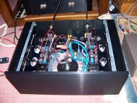
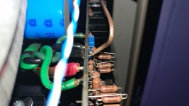
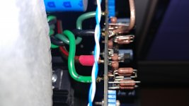
in the end I got the beast biased up.
Space is very tight in this 4U chassis.
Have to find something to vertically
mount the transformer and better position
the diode bridges.
So, how does it sound?
My fave has been then the F4.
I have yet to do a back & forth
with the two, but it may be my
new fav amp.
Seems to reveal more detail/nuance.
Searching for an apt discription and
will say it is less congested during
bursts with a lot going on, ease/coherent?
I like it .
.
Listened to it first with the B1Korg,
but going direct in from the Twisted
Pear SABRE-PRO38, sounds cleaner
revealing more.
My gratitude to Mr. Pass for giving
us yet another superb amplifier.
My only regret is waiting two+ years
since buying it from the diyaudio store.
It was a knock down dragged out battle
but, in the end I got the beast
biased up. Space is very tight in this 4U chassis.
Have to find something to vertically
mount the transformer and better position
the diode bridges.
So, how does it sound?
My fave has been then the F4.
I have yet to do a back & forth
with the two, but it may be my
new fav amp.
Seems to reveal more detail/nuance.
Searching for an apt discription and
will say it is less congested during
bursts with a lot going on, ease/coherent?
I like it
. Listened to it first with the B1Korg,
but going direct in from the Twisted
Pear SABRE-PRO38, sounds cleaner
revealing more.
My gratitude to Mr. Pass for giving
us yet another superb amplifier.
My only regret is waiting two+ years
since buying it from the diyaudio store.
Attachments
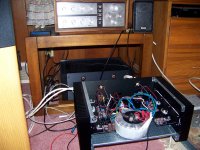

B1Korg is fronting the F4.
Still have to pit the two, F4 vs VFet,
against each other.
At the moment listening to the VFet.
Still have to pit the two, F4 vs VFet,
against each other.
At the moment listening to the VFet.
@ichiban
whatever you say about F4 , 90% of that is about preceding stage ( preamp) , 10% about F4 itself
I'm just being picky , expecting that Greedy Boy(z) always say what's in front , when speaking of F4
glad that you are enjoying your new Papamp
Thank you guys I am happy to say that the amp is now biased up and running. I have been listening to it in conjunction with the B1 Nutube a marriage made in heaven imho. A huge thank you to Nelson for releasing these to the diy community. Like ichiban it has taken me two years to finally complete the vfet amp.
.jpg")
.jpg")
Thank you guys I am happy to say that the amp is now biased up and running. I have been listening to it in conjunction with the B1 Nutube a marriage made in heaven imho. A huge thank you to Nelson for releasing these to the diy community. Like ichiban it has taken me two years to finally complete the vfet amp.
View attachment 767886
View attachment 767887
Great! Let us know your impressions with your DCG3.
nash
Thank you guys I am happy to say that the amp is now biased up and running. I have been listening to it in conjunction with the B1 Nutube a marriage made in heaven imho. A huge thank you to Nelson for releasing these to the diy community. Like ichiban it has taken me two years to finally complete the vfet amp.
Congrats! Looks like a U5 case?
@nashbap I will. The pic I posted shows the pre as a DCG3; really must remove the decals but actually contains the B1 nutube. The DCG3 has been rehoused in a wider case to allow the use of Salas Ubib regs.
@ ichiban it is an 4U 300mm case and runs comfortably at 44/45C after several hours of playing music.
@ ichiban it is an 4U 300mm case and runs comfortably at 44/45C after several hours of playing music.
@ ichiban it is an 4U 300mm case and runs comfortably at 44/45C after several hours of playing music.
Transformer is under the caps?
I was thrown off the size by how
much more space yours seems to
show compared to my layout.
Transformer is under the caps?
I was thrown off the size by how
much more space yours seems to
show compared to my layout.
Yes the transformer is partly covered by the cviller cap board; rectifiers are mounted on the back of the front panel.
Nash thanks for the tip re lifting R19/20 worked a treat.
Last edited:
Biasing one channel, smoke out
I was able to bias up one channel last night.
Tonight, however, I let some smoke out of the other side. Upon looking, I had soldered C8 the wrong way. R30 let the smoke out.
The power was on for a second or two. The cap does not appear damaged. The resistor is gone. Any recommendations on what I should replace before powering on again.
Thanks
(kit from diyaudio.com)
Last edited:
Good afternoon,
I am currently rebuilding the PSU of my mighty V-Fet Amp. When I dismantled the amp, I saw that I'd used veryvery thin cables form the PSU to the amp pcbs and from the amp pcbs to the speaker terminals. The reason were the small bores on the pcbs for that and I wanted to change this now. Since there is no plan to enlarge the bores ;-) I was lookin for cable shoes that other end fit the bores but I couldn'T find some :-(
So what I made me happy, if some experinced guys here might show their solution.
Cheers, Ernst
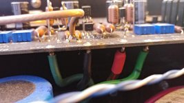
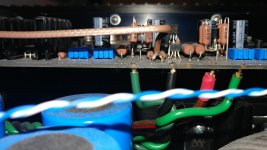
It's a bit hard to capture, but take a look at the attached pics. When the pcb eyelets are too small for the cable diameter I want to use, after stripping the insulation I simply remove as many of the exposed litz wires as necessary to be able to fit the remaining ones in the hole.
In other words, don't use all the strands for making the solder connection, just as many as fit the eyelet, and cut off the rest (before soldering of course).
In other words, don't use all the strands for making the solder connection, just as many as fit the eyelet, and cut off the rest (before soldering of course).
Attachments
It's a bit hard to capture, but take a look at the attached pics. When the pcb eyelets are too small for the cable diameter I want to use, after stripping the insulation I simply remove as many of the exposed litz wires as necessary to be able to fit the remaining ones in the hole.
In other words, don't use all the strands for making the solder connection, just as many as fit the eyelet, and cut off the rest (before soldering of course).
I do the same thing, but wish PC board designers would up the hole size to at least 14 gauge wire. Or give us two holes for each connection with a larger one.
Rush
- Home
- Amplifiers
- Pass Labs
- Sony vFET Illustrated build guide