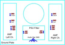
GND connection
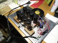
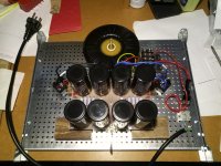
as I am slowly progressing with the amp and have now finished the PSU using 4pole caps I have a question regarding the GND connections:
is it better to use the audio ground (star GND at the PSU) for the speaker connections and connect only the "+ output" from the amp pcb, or use both the "GND and +output" on the amp pcb?
The same same question is also for wiring the input connections ;-)
best regards
Attachments
")
look no further than on how Papa made it
many thanks MZ! it means wiring the GND for input and ouput from the amp PCB and not from the audio star GND at the PSU?
regards
Hi,
I will report was happened, the right chanel is blowing fuse when I try the part 4 (after connection the vfet). The variac do a strange noise! I was thinking perhaps there is a short somewhere, I replace all the mica sheets from the vfet and the mosfet. I did again part3 without any problem but when i started the variac for part 4 the strange noise appear again and I stopped I didn't go further.
I tried in the left chanel, I did again part3 to be sure all was alright, it took time to stabilize r5 = 1.502 r6 = 1.502 and 18 = 0.0336 v. I start part4 and I got rigth away r32 = 101. and DC offset at the speaker terminal 0.0262 v I'm letting warm up before I will do any adjustments.
I don't know what to do in the right chanel!
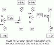
Honestly, at this point I would verify that your VFETs are still viable.
See attached diagrams. The gate voltage MUST be present before you apply any voltage across source-drain. Adjust gate voltage to start passing current though the VFET (mount to some kind of heatspreader), bonus points for measuring Vgs @ 0.5A Ids (which should correspond to the number written on your VFETs).
See attached diagrams. The gate voltage MUST be present before you apply any voltage across source-drain. Adjust gate voltage to start passing current though the VFET (mount to some kind of heatspreader), bonus points for measuring Vgs @ 0.5A Ids (which should correspond to the number written on your VFETs).
Attachments
Good catch, delecoy.
Page 9 of the DIY Sony VFET article reads as follows:
"I suggest that you raise the AC line to voltage over a period of less than 5
seconds."
If you go too slow I think the gate bias which is supposed to turn off the VFETs isn't there, thus they'll conduct whatever is available.
Still, if it works for one channel, and doesn't for the other, I'd check that channel's VFETs.
I used always a variac and I respect all the instructions, I read again before I power on.
I had this problem from the beginning but I started with 1A fuse I thought it was normal! and I tried with 1.25A etc
I completed one chanel
I got R5 = 1.546 V
R6 = 1.541 V
R32 = 0.1008 V
DC at speaker terminal = 0.1 mV !
Does matter if R5 and R6 > 1.5 V ?
I used an headphone connected to the speaker terminal and It sound great (just one chanel), I don't heard any humm o noise, I power with my Dap plenue1 and have not been able to up
at the maximum because it was to loud.
Thanks. Rodeodave i will follow your advise but i'm moving oversea at the end of the month and i have to pack the amplifier tomorrow, and I don't have any bench power supply on hand.
I will have to wait to test it, I did already with a voltmeter following Sony instructions but I know is not as accurate.
Unfortunately this sort of condition is difficult to verify completely without a curve tracer.
You can in principle measure if the VFET works using an ohm-meter and a 9V battery with 1k resistor in series.
The ohm meter is connected to D-S (+ on D for K60, - on D for J18).
The battery with 1k in series (there MUST be a resistor in series to guard against an incorrect connection) goes between G and S (+ on S for K60, - on S for J18).
Here is how you measure:
1) Just use your instrument to verify a diode between D-G and S-G. If the VFET does not pass this test, it is dead.
2) Connect S to G (you can use a short circuit, but even better is if you use the 1k resistor). Then measure resistance between D and S (instrument + on D for K60, - on D for J 60). The VFETs should measure 1-2 ohms (depends on the current the instrument passes through the device under test). If it's radically different, the VFET is dead.
3) Connect 9V battery in series with 1k resistor between G and S (battery + on S for K60, - on S for J18). Then measure resistance between D and S as above. The resistance should be MUCH higher than in step 2 - depending on your instrument it can varu a lot but it will at least be tens of k ohms, usually it will show open circuit. If it shows a low resistance the VFET is dead.
HOWEVER. When Vgs=0V and resistance measured is in the low ohm values but not below 2 ohms, there may be a problem with leakage or breakdown damage which results in dramatic reduction of gate sensitivity, and low Vdg and Vds breakdown voltage. This is not easy to measure but a curve tracer will show it immediately.
Specifically regarding TA-N7: PREVENTIVELY REPLACE THE BIPOLAR OUTPUT TRANSISTORS which are used in the BJT-VFET cascode output stage. I've written about this before, to make a long story short, these tend to break down and in various ways take the VFET with them. If they go short or leaky, they can easily destroy a VFET by simply making it permanently on. If they go open, a more insidious mechanism results, that degrades the VFET very similar to your symptoms by provoking Vgs larger than the specified maximum. In time, the VFET gate to channel interface breaks down and the VFET will start behaving strangely, leaking and resulting in full breakdown of it's mated BJT, in turn destroying both.
The preferred substitutions are D44H11 and D45H11.
I followed the 3 steps and there is hope, the 2 vfet had passed the test successfully!
OK, I am finally begging this thing....
Ordered All This stuff some while ago and am beginning to read up and figure out what I need. Attached is a pic of the kit I received. It seems like there were some other parts kits available back then, but this was the only one I could lay my hands on.
A few questions about needed stuff if I may:
I know I will need these pieces:
UMS compatible TO3 mounting brackets (US warehouse) – diyAudio Store
which are out of stock, hopefully there will be more?
Is there a BOM of all the parts I need to acquire, I see one referred to in a few posts but have not located it.
Is it the 4U "jack of all trades chassis in the build guide, or the 5U?
I notice what looks like white sockets that the V-Fets plug into, can these still be obtained?
I've got a bunch of reading to do!
Russellc
Attachments
![IMG_4676[1].JPG](/community/data/attachments/621/621647-59bda8f40dfce15cadefd250e124a4a0.jpg)
Last edited:
Hi Russellc,
Here's a BOM:
http://www.diyaudio.com/forums/pass-labs/276711-sony-vfet-amplifier-2-a-277.html#post4991406
One thing worth mentioning is that if one is using Fairchild mosfets for Q5 and
Q6 then one likely will need to increase P3 and P4, say to 1K.
Cheers,
Dennis
Here's a BOM:
http://www.diyaudio.com/forums/pass-labs/276711-sony-vfet-amplifier-2-a-277.html#post4991406
One thing worth mentioning is that if one is using Fairchild mosfets for Q5 and
Q6 then one likely will need to increase P3 and P4, say to 1K.
Cheers,
Dennis
Hi Russellc,
Here's a BOM:
http://www.diyaudio.com/forums/pass-labs/276711-sony-vfet-amplifier-2-a-277.html#post4991406
One thing worth mentioning is that if one is using Fairchild mosfets for Q5 and
Q6 then one likely will need to increase P3 and P4, say to 1K.
Cheers,
Dennis
AHHH, similar the the BA3 deal when substituting those pieces. I think I have sufficient pieces for this project without going to the Fairchilds. I have several projects, mono Block BBA3 amps and a few others I obtained them for. Otherwise i will use Fairchild and adjust pot value as you say.
Thanks for the BOM, I can now start a parts box. Did you use the 4U or the 5U chassis?
Russellc
Hi Russellc, 4U is plenty enough. The amps bias is just 1A, so a lot less than other FW amps. It never gets really hot, just warm.AHHH, similar the the BA3 deal when substituting those pieces. I think I have sufficient pieces for this project without going to the Fairchilds. I have several projects, mono Block BBA3 amps and a few others I obtained them for. Otherwise i will use Fairchild and adjust pot value as you say.
Thanks for the BOM, I can now start a parts box. Did you use the 4U or the 5U chassis?
Russellc
Cheers, Ernst
I notice what looks like white sockets that the V-Fets plug into, can these still be obtained?
Russellc
I bought them from ebay.
Nylon/ABS Round Spacer, Not-Threaded, for M3 M4 Screw, ID3.2 / 4.2mm | eBay
Not seeing BOM...
Russellc
Strange. Anyway, it's post #2766 by Variac in the "Sony VFET Amplifier Part 2"
thread. It's a pdf attachment called "VFET Supplemental BOM Store.pdf"
- Home
- Amplifiers
- Pass Labs
- Sony vFET Illustrated build guide