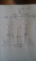
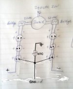
OK - Im not very good at mentally sussing out power supply requirements to please bear with me. I'm not totally sure what I am aiming for here. I have followed the general gist of the post on page 1 of this thread to build the powersupply. I have done it as per the attached. Is this right? I take it Im not aiming for plus 30-0-minus 30VDC? As I dont have that currently. I am getting:
* 30VDC between the wires on each side on the powersupply and
* As well as the above, plus 30VDC between ground and plus on one side and
* As well as the above, minus 30VDC between ground and minus on the other side.
Am I overthinking this? I basically have the same powersupply sorted out as per the diagram in this thread except without the resistors. Would I be better off installing the universal power supply boards sold in the diyaudio store? Im not sure that I have room in my case now.....thanks!
Attachments
Last edited:
Okaaaaaaaayyyyy!
Great - thanks - and I assume that the plus, gnd and minus in your revised diagram goes identically to both modules?
Sorry but I can be a muppet sometimes.
if you're having dedicated PSU per channel , then yes ....... if that is what you're asking
I manage to get original black anodized TO-3 brackets, PCBoards and VFETs but without anything for mounting.
Can owners of ESSENTIALS kit tell what was in the mounting hardware pack?
Need to know type of bolts and their size and size of washers for TO-3 bracket.
And also what type of screws should mount Q5, Q6 transistors heatsink?
M4 are too big, M3 too small. Should be something like M3.5 maybe?
TO-3 brackets have 4 mm holes pre-drilled to mount UMS compatible heatsink.
Tried M4 bolts and they fit just right.
But by Universal Mounting Specification Deluxe 4U and 5U chassis heatsink should be pre-drilled for M3 bolts/screws.
So should there be kind of washers for bracket's UMS mounting holes?
I was planning to buy Deluxe 4U case for Amp in future.
Thank you, Ben Mah.
Most of the answers is found and other will be found eventually.
UMS heatsink mounting hardware contains of M3 screw, lock washer, washer.
There are no length sizes but heatsink is 5 mm thick and UMS heatsink is 1.5 mm thick with a threads tapped to a minimum depth of 5mm.
So 10 mm length M3 screw would be OK.
Although T-bracket UMS predrilled holes are much bigger than M3 screws I did not saw any complains.
I guess it's kind of OK too.
V-FET's mounting hardware contains of bolt, small washer, lock washer, nut and insulator.
No sizes but M4 bolts fit.
Length of bolts used on photos are bigger than needed, about 15-20 mm.
Since T-bracket is 5 mm thick insulator should have 5 mm length.
Predrilled holes for V-FET's are 7 mm so insulator should thick as this or less.
Q7, Q9 transistors mounting hardware contains of bolt, big washer, small washer, lock washer.
M4 bolt fits predrilled T-bracket 4 mm hole.
But by Vishay IRFP240 datasheet transistor mounting hole are 3.51-3.66 mm so bolts are M3.
Transistor is about 5 mm thick, T-bracket 5 mm plus nut and washers.
So bolt length should be about 20-25 mm.
Q5, Q6 transistors heatsink mounting hardware contains of screw, washer, small washer, lock washer and plastiс shoulder washer for transistors with exposed metal tab.
Found mounting kit for this in the BOM.
I have done the setup of the front end on one channel. All went to plan nicely except: Is a reading of .8VDC between Ground and T18 a cause for concern? Its meant to be "fairly close to 0V," according to the instructions. Is this "close?"
Actually after a few more minutes it dropped to .4VDC. This particular reading seems to be the most "dynamic", otherwise the bias stability is really impressive. Thanks!
Actually after a few more minutes it dropped to .4VDC. This particular reading seems to be the most "dynamic", otherwise the bias stability is really impressive. Thanks!
Last edited:
Could I get your views on this please.....?
Referring to Nelsons' post #3116 in the other thread for this amplifier -
Sony VFET Amplifier Part 2
Where he said: I think you're OK. If the VFETs aren't installed, then there is no feedback
to the front end - you are seeing the offset "open loop", and the level
of accuracy on DC is as good or better than you should expect. This should clear up after the VFETs are installed.
I have re-done my set-up and bias procedure for one board - all measurements are perfect - I had to increase P3 & P4 myself to get up to 1.5V between T6 to T7 and T8 to T9. This was done over a period of about 1 hour.
However as per my above post, the DC offset is higher than it was before - I have now reached the 1.5V as shown above, however I have 2.8V between Ground and T18 - does Nelson's advice still apply, given that I have fairly significant voltage here?
See also post 259 of this thread......
I ran thru the setup procedure again and now have the offset at about 1.7V.
thanks!
Last edited:
")
hi everybody
i was wondering if someone had already time to tune a bit around this nice amp and can report? or if something is already perfect we can not make it more perfect :-D
best regards
In post #2630 of the VFET pt2 thread you can see my implementation of the voltage regulator circuit for the cascode transistors.
I also used 5R source degeneration resistors for the J74 to get a better complementary match with the K170.
http://www.diyaudio.com/forums/pass-labs/276711-sony-vfet-amplifier-2-a-263.html#post4975031
Both mods were fun to do and help me sleep better at night.
there is slight dilemma ....... did Papa strive for perfect symmetry ...
considering latest experiments ....... not so sure he did ......

Most likely he didn't, but we can tweak this, can we?
Hello,
Thank you so much for all the awesome build guide and all the info. I am looking forward to hear the amp, and finally got around to start assembling the kit. Have a couple of questions;
Speaker connection? Cannot see a point on the board.
The other issue I have is DC from G-18 on the board. When powering up takes very long to slowly come down. Starting with 0.5V the gradually comes down to around 150~200mV. When amp is up and running I can adjust under 50mV, next time powering up same thing happens. My transformer has 24v secondaries and I get just a little above 32v on each sides of the PSU. Caps are 15000 63v
- Home
- Amplifiers
- Pass Labs
- Sony vFET Illustrated build guide