Sorry....missed your question about T4-GND. That's problematic.
I assume you have roughly +/-28V rails. Please check soldering around
Q14, R16, R18, R20 and that you have the correct value parts there.
The T4-GND voltage there means Q14 is not working. If the resistor values
and soldering are ok then you should replace Q14.
I would try changing the R34/R35 values rather than changing the jfets. (I'm
hesitant to risk damaging them by desoldering.) Do you have any low value
resistors (say 100ohm)?
OK, I took a break and went back to this. With 100 ohm in R34 and R35, I am able to adjust P3 to get the T6-T7 voltage to 0.07v. So I think it's OK - coorect?
Now I just need to find the problem with T4 to Gnd voltage, but I haven't looked. Will take a look in the morning and report back.
Now I just need to find the problem with T4 to Gnd voltage, but I haven't looked. Will take a look in the morning and report back.
So you now have an adjustment range of .07 volts to 7.2 volts or 1.5 ma to 152 ma.")
The TL 431 regulator, if working properly should have a 2.5 volt reference which appears across R18.
2.5v/4750(R18)=0.05 ma. 0.05 x 41,200(R16)=21.68 volts. Add the two together and you have your 24 volts.
What's the voltage across R20?
The TL 431 regulator, if working properly should have a 2.5 volt reference which appears across R18.
2.5v/4750(R18)=0.05 ma. 0.05 x 41,200(R16)=21.68 volts. Add the two together and you have your 24 volts.
What's the voltage across R20?
OK, I took a break and went back to this. With 100 ohm in R34 and R35, I am able to adjust P3 to get the T6-T7 voltage to 0.07v. So I think it's OK - coorect?
T6-T7 and T8-T9 should both be 1.3vdc after alternate P3/P4 adjustment in 100mVdc increment while keeping T18 (input stage out) close to zero. Then allowing it to warm up until you settle temp equilibrium to 1.5vdc as Nelson says in test procedure.
Now I just need to find the problem with T4 to Gnd voltage, but I haven't looked. Will take a look in the morning and report back.
Referencing your photos from post #1178,
https://www.diyaudio.com/forums/pas...-illustrated-build-guide-118.html#post6471335
it looks like Q14 is oriented incorrectly.
Referencing your photos from post #1178,
https://www.diyaudio.com/forums/pas...-illustrated-build-guide-118.html#post6471335
it looks like Q14 is oriented incorrectly.
Good catch Dennis. It was inserted incorrectly. You'd think after all these years I would not make such a stupid mistake. Perhaps old age setting in...
Results: with Q14 installed correctly and R34/35 replaced with 100 ohm resistors, I seem to be getting voltages within range of the results specified by Nelson in his original document. The only possible variance is T6-T11 and T8-T13 - both of which are measuring closer to 9 v than the recommended 5. I'm assuming this is not a problem at this point.
But before I proceed, I want to verify one more point.
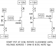
I'm using 2SK60 and 2SJ18 VFETs because I couldn't find the correct ones. From my reading it appears these should work, however they need half the bias. I measured the Vgs using the following circuit from Mr. Pass, but measured Vgs with the voltage across the 1ohm resistor set to .25V instead of .5 shown in the diagram. Using that procedure I have Vgs of:
J18 - 7.4 and 7.7
K60 - 6.2 and 6.9
Before installing VFETs, I will set the bias using these numbers according to the procedure in the original document prior to installing the VFETs.
After installing the VFETs, I set the voltage across R32 to be 50mV instead of 100mV for the original VFETs.
Am I correct in using half the drop when measuring the Vgs and half the voltage across R32? I've read this recommendation in the thread a couple time but want to be sure I don't destroy these scarce VFETs.
Thanks for the continued assistance.
Attachments
- Home
- Amplifiers
- Pass Labs
- Sony vFET Illustrated build guide