Let's see a practical (and working) example:
My toroid about 650VA, it has four pair secondaries with 24VAC, without load.
Each pair of secondaries has a dedicated diode bridge, and capacitor bank of 4x22000Uf/35VDC.
It gives me +/-29.7VDC at the amp +/- input point, there is some loss on paralleled 4xR0.47Ohm of CCRCC power supply.
I have 102-103mV through R32, so there is almost exactly 1A current flow.
Chosen resistor value is 42.2Kohm for R15/R16.
It gives me almost exactly 20VDC on testpoints T3/T5.
I'm wondering, may I go a little higher, say 22-23VDC?

I am just surprised at the degree of voltage loss at the 4x0.47 resistor bank. Yours is a 2.8v drop if we assume a theoretical voltage of 32.5V DC. When I built my F6 power supply, i had a drop of less than 1v DC from theoretical numbers. Maybe my primary voltage was higher than norm (230) or yours is lower than norm. I didnt measure the AC primary and secondary voltages, so i dont know
to solve the dimensioning of the R´s i decided to do the following (that might not be necceceraly right )
the higher the R, the more damping, the more V drop, the more heat dissipation.
As a practical solution, i could start installing 2 parallel 5Watt 0.45R, touch them, and if they are too hot , just add another 2pcs? I guess dimensioning is a kind of trade off between effect (higher R value) and the problems involved with that,(heat dissipation, waste of energy). So the classical 8Rs per PSU Stereo might be a sweetspot more economicalwise that a electrical neccesity?
)the higher the R, the more damping, the more V drop, the more heat dissipation.
As a practical solution, i could start installing 2 parallel 5Watt 0.45R, touch them, and if they are too hot , just add another 2pcs? I guess dimensioning is a kind of trade off between effect (higher R value) and the problems involved with that,(heat dissipation, waste of energy). So the classical 8Rs per PSU Stereo might be a sweetspot more economicalwise that a electrical neccesity?
actually the higher the R, less current will flow through the R, so less heat dissipation ;-)...
the higher the R, the more damping, the more V drop, the more heat dissipation.
...
Please bear in mind, I'm not an EEE mind, but there is something missed.
It is certainly true, if you have a voltage source and you swap R on it to a bigger one, there will be a smaller current flow.
It is true in this special case as well, as you change R in CCRCC to a bigger one, there will be a smaller current flow.
But then you will set bias current of amp to 1A again.
Then there will be a greater voltage drop on R with the same 1A, so there will be more power to dissipate.
I don't know was I understandable.
But I feel I have right.
I have something 0.120mV drop on R of CCRCC.I am just surprised at the degree of voltage loss at the 4x0.47 resistor bank. Yours is a 2.8v drop if we assume a theoretical voltage of 32.5V DC. When I built my F6 power supply, i had a drop of less than 1v DC from theoretical numbers. Maybe my primary voltage was higher than norm (230) or yours is lower than norm. I didnt measure the AC primary and secondary voltages, so i dont know
It is equal 1A current flow on it.
Probably the diode bridge is responsible because of missing volts.
I have something 0.120mV drop on R of CCRCC.
It is equal 1A current flow on it.
Probably the diode bridge is responsible because of missing volts.
Weird. Typical diode bridges drops around 1.4V. I suspect it's lower than normal mains voltage, or there's some losses in the capacitor bank (shouldn't be significant for low ESR types). Anyway, so long it sounds good, who cares !
I decided to get one custom made in China - keeping my fingers crossed on the quality
Just tested my 24V Block transformer, and the output is actually 26V. Which makes sense since they are specced for 2 X 115V (230V tied) primaries, while I have measured my mains at 239V.
So I can't use them. Also Block don't make 20V transformers, else that could have been an option.
Which leaves only Antek and Amplimo, with the resultant shipment expenses. Drek!
BTW, these are my shipping cost options for Antek:
------------------
Please choose the shipping method for your order:
USPS Priority International $73.50
UPS (Worldwide Expedited) $367.84
------------------
And this from Amplimo:
------------------
Shipping
Postal Service World (with tracking !) (+ €58,26)
DHLExpr9 / UPS / FedEx (+ €165,00)
------------------
Curses!
Last edited:
Because it's UPS. I contracted for them a few years ago, I have little good to say about the company as a whole. I avoid using them as much as possible.
But really what you're looking at is their price reflect that they don't want to do it... All the other carrier's options are reasonably priced, so UPS' price has been effective in dissuading you from using them.
But really what you're looking at is their price reflect that they don't want to do it... All the other carrier's options are reasonably priced, so UPS' price has been effective in dissuading you from using them.
Last edited:
Jim
Those Antek AS series transformers: are they bifilar wound transformers with uniformly laid down windings?
I never had one in my hands, so I can't tell. I have one Amplimo 650VA transformer that is winded like that, and I would go for an Amplimo again if the Anteks were not substantially cheaper. It's $137 vs €165 shipped (by slow boat).
Those Antek AS series transformers: are they bifilar wound transformers with uniformly laid down windings?
No idea, they are taped pretty tight, and I've never opened one up.
I like the AS- because the shield needs to be tightly wound around the windings, and then taped tightly to stay on. This means that the Shielded ones have, in my experience, less mechanical hum than the AN- .
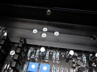
small white TO-3 insulators
Hi Jim
Thanks alot for the build guide - it has really been a great help to me. I have now managed to bias up the front end Mossfets and adjusted the DC offset (G - T18). The amplifier has been running stable for a couple of hours now.
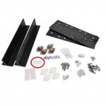
I am now about to install the VFETS but have one doubt. The VFET essential package from diyaudiostore only contained 8 PC's of the small white insulaters - I noticed that even the picture from when I ordered the essential kit also only show 8 pcs. In your build guide it seems 16 pcs are needed (4 insulators per VFET). Can I get along with only 8 insulators or do I need to order additional insulators?
Thanks again - your help is really appreciated
Best Regards
Rolle
Hi Jim
Thanks alot for the build guide - it has really been a great help to me. I have now managed to bias up the front end Mossfets and adjusted the DC offset (G - T18). The amplifier has been running stable for a couple of hours now.
I am now about to install the VFETS but have one doubt. The VFET essential package from diyaudiostore only contained 8 PC's of the small white insulaters - I noticed that even the picture from when I ordered the essential kit also only show 8 pcs. In your build guide it seems 16 pcs are needed (4 insulators per VFET). Can I get along with only 8 insulators or do I need to order additional insulators?
Thanks again - your help is really appreciated
Best Regards
Rolle
Attachments
I didn't build mine from the Kit...
With only 8, I'd use the spacers on the holes with the screws to help align everything.
The pins could be insulated with a bit of wire insulation from stripped ends, small bits of heat shrink, teflon tubing, or something similar. If everything is lined up properly the pins shouldn't touch the metal holes of the T-bar, but having something on the pins would be good insurance.
Is there any benefit in matching Q5 and 6?
I have some 2SK2013 and 2SJ313 FETs in my stash that I can use in place of the supplied Fairchilds.
Not really. Use the Toshibas, no matching is needed as far as I remember.
These work well and allow you to space the board slightly from the bracket.
164004003 UNBRANDED, Spacer, Round, Nylon 6.6, 6x4.5mm | Farnell element14
164004003 UNBRANDED, Spacer, Round, Nylon 6.6, 6x4.5mm | Farnell element14
- Home
- Amplifiers
- Pass Labs
- Sony vFET Illustrated build guide