Thanks for your response, 2 picoDumbs. It was the power supply. I found a spare 24V supply at the office (Dymo switching), and tried it out before testing with batteries. Problem solved. Transparent, clear as day. Wish I'd tried that before tearing it up, but at least the problem was external to my part of the circuit, and my grounding scheme is improved as a result.
With B1R2 in the chain, it's hard to tell any difference with DAC source. But now have heard Jolida JD100 CDP through the F6 for the first time. I like the hint of tube warmth with the F6 via B1R2.
With B1R2 in the chain, it's hard to tell any difference with DAC source. But now have heard Jolida JD100 CDP through the F6 for the first time. I like the hint of tube warmth with the F6 via B1R2.
If the devices operate at their Idss then the current draw is the Idss.
Thus you select your two Idss and that becomes your current draw.
For stereo you double that.
The Rev2 has source resistors built in.
Effectively they are 25ohms in each source and this will make the two jFETs operate at well below their Idss.
If you measure them before you fit them in you can find the Id when Rs=25r
This new Id becomes the current draw.
Last edited:
Assume you have a B1 Rev2 in LtSpice...The input is closely followed with volume control input resistor (P101) and then big value resistor to ground (R104) to set input impedance and then perhaps another (R103) and then into the gates.
If you want to float this complementary pair buffer, is there any reason why you can't put a small value cap just prior to the gate resistor (R103). It seems to drive Spice nuts...
If you want to float this complementary pair buffer, is there any reason why you can't put a small value cap just prior to the gate resistor (R103). It seems to drive Spice nuts...
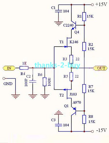
referring to schm in your post (#146)
you can leave C1 and C3 in , toss C2 out
leave out R1, R2 , R7,R8
leave out Q4 and Q1 , put shorts through C-E holes
and that's it - B1 V2
depending of your JFets Idss , you can put shorts instead of R3 and R5 , or decrease them to 10R ...... or put 20R trimpot between sources , with wiper to out , if you need to trim output offset
Being a bit perfectionist, I am curious what's the better way to go.
I am playing with B1 v2 buffer with two 22 Ohm source resistors instead of 50 Ohm pot.
My 2SK170 is 7.89mA Idss en when I put in identical matched 2SJ74 with 7.89mA, I always have an offset of 10-12mV.
To get it to zero offset, I can do two things:
1. Put in a 2SJ74 with around 8.60mA Idss, which gives almost zero, 0.5mV offset.
2. Put a 200 Ohm trimmer over the source resistors, like in F5T, and trim the matched JFET's offset to zero.
With 1. problem is you can hardly call that matched JFET's, 0.7mA difference. As we know 2SJ74 has already higher Yfs, so choosing a 0.7mA higher Idss JFET would only make the Yfs difference more worst.
With 2. problem is, when I measure the resulting source resistors after trimming, the K170 is 19 Ohm and the J74 resistor is 15 Ohm. So K170 is more degenerated than the J74. For Yfs also not ideal.
What is the way to get zero offset, and get the best performing buffer, use identical JFET's and put 200Ohm pot over source resistors?
Or use a 0.7mA higher Idss 2SJ74?
I am playing with B1 v2 buffer with two 22 Ohm source resistors instead of 50 Ohm pot.
My 2SK170 is 7.89mA Idss en when I put in identical matched 2SJ74 with 7.89mA, I always have an offset of 10-12mV.
To get it to zero offset, I can do two things:
1. Put in a 2SJ74 with around 8.60mA Idss, which gives almost zero, 0.5mV offset.
2. Put a 200 Ohm trimmer over the source resistors, like in F5T, and trim the matched JFET's offset to zero.
With 1. problem is you can hardly call that matched JFET's, 0.7mA difference.
As we know 2SJ74 has already higher Yfs, so choosing a 0.7mA higher Idss JFET would only make the Yfs difference more worst.With 2. problem is, when I measure the resulting source resistors after trimming, the K170 is 19 Ohm and the J74 resistor is 15 Ohm. So K170 is more degenerated than the J74. For Yfs also not ideal.
What is the way to get zero offset, and get the best performing buffer, use identical JFET's and put 200Ohm pot over source resistors?
Or use a 0.7mA higher Idss 2SJ74?
Last edited:
match them , while enjoying in coffee and beer
then set output offset with 20R trimpot,while enjoying in coffee and beer
then enjoy in plenty of music , with or without coffee and beer
remember - you're not making life supporting equipment ....... at least not commercial one
then set output offset with 20R trimpot,while enjoying in coffee and beer
then enjoy in plenty of music , with or without coffee and beer
remember - you're not making life supporting equipment ....... at least not commercial one
In this arrangement AC and DC parameter of circuit is not separated, so
you must to trim offset to minimum and you have what you have.
No freedom for sound adjustment.
Much more funny is to place coupling cap to output and extend potentiometer shaft to front plate In that case you can adjust sound with pot.....
..... positiv 2nd, negativ 2nd, nulling...
you must to trim offset to minimum and you have what you have.
No freedom for sound adjustment.
Much more funny is to place coupling cap to output and extend potentiometer shaft to front plate
In that case you can adjust sound with pot.......... positiv 2nd, negativ 2nd, nulling...
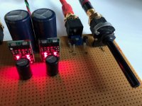
While waiting for the B1 Nutube edition I put the B1 rev 2 together.
I followed Mr. Pass' general rule: 'use what you have'.
I only had 500 Ohm trimmers so each leg is paralleled with a resistor to bring the resistance down.
The PSU is made of one SilentSwitcher (see the store) followed by a pair of Hypex regs to bring the voltages down to +/-12V. The SilentSwitcher is powered by a USB power bank.
I'll be delighted if the B1 Nutube is any better than this one 'cause its damn good as it is. Go Build 1 yourself.
Attachments
it is a "JFET input Cascoded Buffer Board" for a few $ from ebay.
It should be a piece of cake to use for the b1 rev 2 (with an external supply pcb), but there are a few parts more on this pcb. What do you thing about those?
I bought some of these for amusement. The objective performance is good. -3dB at around 1.8 MHZ. Output impedance around 1k ohm. These could easily be operated at the +/- 24V rails of the First Watt amplifiers. I will test these with the Edcor transformers purchased for the M2X.
(QUOTE\ I'll be delighted if the B1 Nutube is any better than this one 'cause its damn good as it is. Go Build 1 yourself.[/QUOTE])
The B1 v2 is my go to volume control for all my amplfiiers. I have the Pete Millett Nutube version and it and NP Nutube pre are what NP calls sound effect devices which introduces some 2nd harmonic for those that like such. I rarely use the Nutube but it was fun to build and I am glad I have it.
The B1 v2 is my go to volume control for all my amplfiiers. I have the Pete Millett Nutube version and it and NP Nutube pre are what NP calls sound effect devices which introduces some 2nd harmonic for those that like such. I rarely use the Nutube but it was fun to build and I am glad I have it.
something is fishy there
Rout needs to be roughly (1/Yfs)/2 , if you got genuine JFets
Thanks for the formula. I will take measurements again and post the procedure and results. I can also do the procedure an a matched set of Punkydawgs genuine K170/J74.
Pass B1R2 buffer with power supply
I've made a PCB with an LT1086/1033 regulator and Pass B1R2 buffer, details here:
Pass B1R2 Buffer - mpbarneyamps
Mike
I've made a PCB with an LT1086/1033 regulator and Pass B1R2 buffer, details here:
Pass B1R2 Buffer - mpbarneyamps
Mike
- Home
- Amplifiers
- Pass Labs
- B1 Rev. 2