Hello.
I assume that this is the right procedure, when testing/powering up ::
Short -IN and +IN to GND
Plug in mains (Variac, lightbulb is only for Sissy)
PSU is +18 - "0" -18 VDC
Meassure voltagedrop across R16 (Source resistor Q5)
This is BIAS, but howto calculate this ???
I expect this voltage to be around 0.5V for Bias >1A ???
Bias is adjusted with R27 trimmer.
When everything is good, also adjust DC-offset with R7 trimmer.
Normal procedure after that, let amp. warm up and settle, then readjust and see if everything is stable and temperature is not to hot (>55C)
Jesper.

pretty much - yes
also , it helps if you have mosfets mounted on heatsink

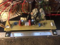
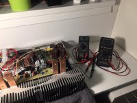
Initial test success AlephJ_Mimi!
Hello.
I powered up our little AlephJ (Renamed to Alepj_Mimi!)
Accecdentily i renamed some pictures to _Mimi!, so hereby a new name... tadaa : AlephJ_Mimi! ... Cool yes ?
Some of the parts are slightly different from schematic, but not much; i will ofcause post that later on, when prober testing is done.
Bias is easily adjusted, up/down around 0.6V (1,27A Bias)... I figured out that voltage divided by sourceresistor (eg. 0.6/0.47 = 1.2A)... Silly me i should have know that before i asked that yesterday Sry...
After a short while, without prober heatsinking devices are heating up. DC-offset was a little jumpy for a start, but after 30sec. it was also good enough to adjust... So i guess circuit is working.
Next week i will try mounting heatsinks, and ofcause adjust the thing for good.
Thanks everybody for helping me, get this far by now.
Good sunday!
Jesper.
Hello.I powered up our little AlephJ (Renamed to Alepj_Mimi!)
Accecdentily i renamed some pictures to _Mimi!, so hereby a new name... tadaa : AlephJ_Mimi! ... Cool yes ?
Some of the parts are slightly different from schematic, but not much; i will ofcause post that later on, when prober testing is done.
Bias is easily adjusted, up/down around 0.6V (1,27A Bias)... I figured out that voltage divided by sourceresistor (eg. 0.6/0.47 = 1.2A)... Silly me i should have know that before i asked that yesterday Sry...
After a short while, without prober heatsinking devices are heating up. DC-offset was a little jumpy for a start, but after 30sec. it was also good enough to adjust... So i guess circuit is working.
Next week i will try mounting heatsinks, and ofcause adjust the thing for good.
Thanks everybody for helping me, get this far by now.
Good sunday!
Jesper.
Attachments
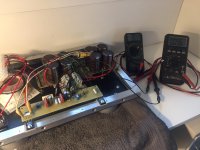
Setting Bias
Morning.
I have mounted some heatsinks, which size should match the dissipation (i hope), for our MiniAmp. here.
Rail is with this PSU ~ -19 "0" +19 vdc.
I tried setting bias at 0.61 (~1.3A), but source resistors/mosfets are getting hot to the touch. Setting Bias around 0.51 (~1A) is much better.
I just remember, that i read somewhere Bias should be set to no less than 1.2A ? -Can't remember where i read this? -And why?
Can someone comment on this ?
- I mean, what is pros and cons ?
- Later today i will try listning to some recordings, to hear if Amp. is swinging enough watts for my setup!
Really exciting Looking forward to this test.
Jesper.
Morning.
I have mounted some heatsinks, which size should match the dissipation (i hope), for our MiniAmp. here.
Rail is with this PSU ~ -19 "0" +19 vdc.
I tried setting bias at 0.61 (~1.3A), but source resistors/mosfets are getting hot to the touch. Setting Bias around 0.51 (~1A) is much better.
I just remember, that i read somewhere Bias should be set to no less than 1.2A ? -Can't remember where i read this? -And why?
Can someone comment on this ?
- I mean, what is pros and cons ?
- Later today i will try listning to some recordings, to hear if Amp. is swinging enough watts for my setup!
Really exciting
Looking forward to this test. Jesper.
Attachments
At 1.3 A, 0.47Ohm resistor is only dissipating 1.3 x 1.3 x 0.47 = 0.8Watts
Set at 1.3A and stop worrying about it.
This is a single ended amp (not push pull), you want as much bias current as the mosfets, and your heatsinks allow, so set at 1.3A and stop worrying about it.
Set at 1.3A and stop worrying about it.
This is a single ended amp (not push pull), you want as much bias current as the mosfets, and your heatsinks allow, so set at 1.3A and stop worrying about it.
all Danes are having same heatsinks

You allready know that ZM
...I am lucky, that mine is partly, so i can use lower half, for making a lower chassis.
Jesper.
At 1.3 A, 0.47Ohm resistor is only dissipating 1.3 x 1.3 x 0.47 = 0.8Watts
Set at 1.3A and stop worrying about it.
This is a single ended amp (not push pull), you want as much bias current as the mosfets, and your heatsinks allow, so set at 1.3A and stop worrying about it.
Hi.
I see the point here.
Running at 1.3A will give near 25w pro mosfet, and 100w for stereo, which is i think perfect.
I will start it up again and cranck bias to 0.6 now...
Too be continuied
Jesper.
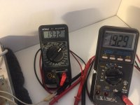
One channel up
Maybee....
But https://www.youtube.com/watch?v=nzkubfTPDaU ...
AlephJ Mimi is now set at Bias ~1,3A.(NON Sissy Bias) DC-offset is pending up/down very stable near "0"...
Going much higher on volume on my DCG3 (2xgain) preamp will be to much Speaker(s) are 90dB
I am really amazed by first impression!... not that i can tell anything about soundquality, but amp. is completely quiet; even with all cables messed up like a birds nest
So we (*I) now know that amp. is giving enough gain/voltageswing for my system to be played to the max. -Perfect.
Hope you enjoy my video... just for fun
Jesper.
aha
in spirit of the day , you can name it Aleph SissyJ

Maybee....
But https://www.youtube.com/watch?v=nzkubfTPDaU ...
AlephJ Mimi is now set at Bias ~1,3A.(NON Sissy Bias) DC-offset is pending up/down very stable near "0"...
Going much higher on volume on my DCG3 (2xgain) preamp will be to much
Speaker(s) are 90dBI am really amazed by first impression!... not that i can tell anything about soundquality, but amp. is completely quiet; even with all cables messed up like a birds nest
So we (*I) now know that amp. is giving enough gain/voltageswing for my system to be played to the max. -Perfect.
Hope you enjoy my video... just for fun
Jesper.
Any chance of the boards being available ?
Hello.
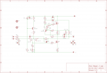
The board is only proto (one channel); and i need Didiet78 to make some small changes for me. -The board i created is also NON ums (non diyaudio standerd), so this also have to be considered.
Some of mine precious parts (some capacitors and the 2sj109V) is also parts, which should not be made in a "groupbuy" or like pcb i think.
But i think Didiet78 also have an UMS board ready by now.
I will take contact with the pcbmaster
later tonight!, and see if he is able to make some small changes for me?Let's see future on, i am not nearly finish yet.
Thanks for following my thread
Jesper.
Any chance of the boards being available ?
Standard Aleph J availabe on DIY Audio Store
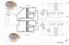
Dual torrids possible in firstwatt PSU ?
Hello.
For testing two channels, i need a bigger torrid than the one 120VA i got now.
I am planning to do dual PSU in one chassis.
I can still source a torid like the one i allready got, so two identical torrids.
But i am in doubt if it's possible to use two torrids on the same PSU, for testing.
It will be some time before i will make new psu boards, so testing with my old one, would be nice!
Anybody know that???
0120P1-2-015 | 2 Output Toroidal Transformer, 120VA, 2 x 15V ac | Nuvotem Talema
Jesper.
Attachments
I would believe them (enough for paralleling of secondaries) only if they're wound bifilary
in any other case , each secondary get dedicated bridge , then do whatever you want
good thing is that you can use smaller bridges for that
So looking at datasheet of that torrid, say's parallel and seriel is possible.
I also once paralled a torid, without problems.
Quistion is more about, how psu is reacting on this?
Product Details
Open Style with Leads, 15VA to 1000VA
High quality open style toroidal transformers with a single 230Vac 50/60Hz primary winding. Twin secondary windings may be connected in series or parallel or used independently.
- Status
- This old topic is closed. If you want to reopen this topic, contact a moderator using the "Report Post" button.
- Home
- Amplifiers
- Pass Labs
- AlephJ Mimi! (Mini)