
Yes...
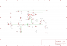
I am using 25x turn one's- I will just put maybee 5-10K in front of the 100K trimmer for avoiding "0" ohm. - Well maybe just i use a short, i allways place such trimmer halfway anyway

Speaking of sissy... guess what's used when painting the big Cu traces
Jesper
I am using 25x turn one's- I will just put maybee 5-10K in front of the 100K trimmer for avoiding "0" ohm. - Well maybe just i use a short, i allways place such trimmer halfway anyway
only Papa is versed enough to use simple turn pots , everyone else is sissy
Speaking of sissy... guess what's used when painting the big Cu traces
Jesper
Attachments

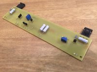
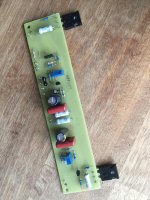
be careful with mosfet mounting
it's easy to pill out traces , when mosfets are soldered like that ( no support from above)
Yes... I see you are right. Thanks.
Jesper.
Hello Jesper, seems like a nice build!
One question though, what is the function of adding C3 and C6??
I cant tell; but the 220uF is in original schematic.
Jesper.
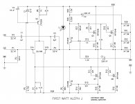
Ok, I think I found the schematics in Jespers earlier post.
http://www.diyaudio.com/forums/pass...j-whatever-maybee-jfet-input.html#post4933856
It is a schematics of First Watt Aleph J (C)2005, there is Q4, if I understand the function of it, is to current limit the output transistors to roughly ~1,5A, but C3 seems to modulate the current limit?
I am lost, maybe you are right Didiet haha...
Mr. Pass, please explain C3!
Attachments
Thanks ZM!
I found a good description how it works, easier reading than patents (# 5,710,522).
https://www.passdiy.com/project/amplifiers/zen-variations-9
I found a good description how it works, easier reading than patents (# 5,710,522).
https://www.passdiy.com/project/amplifiers/zen-variations-9
when testing/setting - ground both inputs , no load on output
when singing - if you use RCA , ground neg input
Ohh yea! i remember now... thanx.
Jesper.
Testing
Hello.
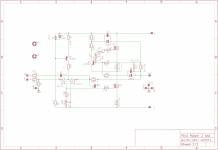
I assume that this is the right procedure, when testing/powering up ::
Short -IN and +IN to GND
Plug in mains (Variac, lightbulb is only for Sissy)
PSU is +18 - "0" -18 VDC
Meassure voltagedrop across R16 (Source resistor Q5)
This is BIAS, but howto calculate this ???
I expect this voltage to be around 0.5V for Bias >1A ???
Bias is adjusted with R27 trimmer.
When everything is good, also adjust DC-offset with R7 trimmer.
Normal procedure after that, let amp. warm up and settle, then readjust and see if everything is stable and temperature is not to hot (>55C)
Jesper.
Hello.
I assume that this is the right procedure, when testing/powering up ::
Short -IN and +IN to GND
Plug in mains (Variac, lightbulb is only for Sissy
)PSU is +18 - "0" -18 VDC
Meassure voltagedrop across R16 (Source resistor Q5)
This is BIAS, but howto calculate this ???
I expect this voltage to be around 0.5V for Bias >1A ???
Bias is adjusted with R27 trimmer.
When everything is good, also adjust DC-offset with R7 trimmer.
Normal procedure after that, let amp. warm up and settle, then readjust and see if everything is stable and temperature is not to hot (>55C)
Jesper.
Attachments
- Status
- This old topic is closed. If you want to reopen this topic, contact a moderator using the "Report Post" button.
- Home
- Amplifiers
- Pass Labs
- AlephJ Mimi! (Mini)