No I'm not.
Safety in numbers.
Thanks ZM
Haha
Push "Safety in numbers" to the limit with 10000 JFETs!

Nice!
I was getting a bit worried by the route this thread was taking as it was "The F4 Beast" after all and we appear to have lost some of the "Beast" part with the smaller output devices.
I'm currently working on another project so I have not made my stereo "Hockey Puck" (with your temp compensation circuit) amplifier running 12A bias yet but once I finish I will post pictures.
Keep up the excellent work.
Just finished reading this thread. A truly awesome collection of efforts and knowledge.
The attached is a different front end driving much the same output devices as in this thread. I am wiring up a breadboard to see if I can get the amp biased and get an output. LT Spice says that about 8.2 v p-p from +/- 5V rails before clipping.
The amp is intended to drive low a resistance ribbon directly.
indra1 set this up in LTSpice and got it dialed in for bias and offset. Many thanks to him.
I am looking for a pair of the hockey pucks that do this job and the P channel units are far behind the N channel units for RDSon.
Attachments

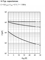
5V rails are ok for testing but you don't want to use 5V in the finished amp.
The capacitance values are terribly non-linear in that region.
The capacitances of the hockey pucks or the capacitances of the front end transistors?
The capacitances of the hockey pucks or the capacitances of the front end transistors?
All of them, the hockeypucks are certainly the most offensive.
The cascoded front end stage is probably the least of your problems though.
Any reason you can't use 15V rails? Then you have 10V of PktoPk signal without issue
The front end and Vas is +/- 24v. The outputs are set a +/- 5V because the load will be a nearly short circuit compared to any ordinary speaker. The worst-case is what is shown in the schematic at 30 milli-ohms and that is a 24" skinny ribbon. A shorter skinny ribbon will be lower resistance.
Any voltage above 5V will be wasting power on the output devices.
Any voltage above 5V will be wasting power on the output devices.
That one looks quite nice.
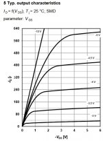
That is the IPB120P04P4L. Its a TO220. I am not certain how good it will be at getting the heat out to the heatsink. They were $2.31 each from Digikey. I bought 10 each of the P and N. If I blow up a few, no big deal.
If you look at the IdVd curve, Vds is 1V at 400A. Thats about 2.5 milliohms RDSon. I cannot find as good of a P part in the hockey puck package.
Attachments
In trying to help woofertester I look for ways to stabilize bias using very low current sensing resistor and came across Hall effect current sensor. The ACS723 attached only have 0.65 mΩ sensing resistance. I posted some sim in Auto-Biasing Circuits for Complementary Followers thread. Could be useful to you guys. I have not tested it yet, but linuxguru in tubes forum have mentioned using similar device to sense cathode current.
Attachments
Ids vs Vgs
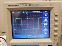
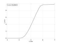
Today I ran some tests on the IPP120N04S4. Attached is the curve for Ids vs Vgs.
The test rig can only go to 10A and the cables from the rig are ridiculously resistive compared the RDSon of the MOSFET.
I just wanted to see where the bias wants to be to get a good running start at the linear portion of the curve. Looks like between 1.5A and 2A bias.
I am currently gathering heatsinks and parts to throw together a prototype.
Attachments
I agree. I have used two approaches:Please be aware that Vds-Id measurement should be done at constant temperature. The curve is temperature dependent.
- Vgs ramp at a sufficiently high frequency, such as 200Hz, that temperature effects are minimal. This requires a way to capture Idrain, such as measuring the voltage across a sense resistor.
- Low duty cycle Vgs pulses of varying pulse height, with the "nominal" level to maintain the desired operating temperature of the FET.
- Home
- Amplifiers
- Pass Labs
- F4 Beast Builders