yeah
as that you don't know ....
(who needs Babelfish one , when I can have Real McKay ........ will repair few of these I already have in OPLDF)
Repairs already.
Either they are selling a lot of these, or failure rate is high.
neither of those (having nothing with failure rate)
white van approach ....... fallen from the truck etc.
Aaaaah clever Zenmod.
Got to learn these code words.

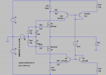
Here is an idea for bias controllers for the output mosfets.
The controllers compensate large differences in threshold voltages of the MOSFETs individually, so no special selection of the MOSFETs (matching) is necessary.
Multiple stages can be connected in parallel, if more output power is necessary.
Amp4o_simplified.asc: Simplified schematic
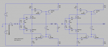
Amp4o_simplifiedparallel.asc:Simplified schematic with parallel output devices
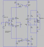
Amp4o_simplifiedccs.asc: schematic with constant current source that compensates changes in power supply voltage. 1mOhm resistors are for simulation purposes only and are replaced by wire.
It is only an idea, not a ready to build schematic. For example bias and supply voltage cause a power dissipation that is too much for the IRP240/9240.
The controllers compensate large differences in threshold voltages of the MOSFETs individually, so no special selection of the MOSFETs (matching) is necessary.
Multiple stages can be connected in parallel, if more output power is necessary.
Amp4o_simplified.asc: Simplified schematic
Amp4o_simplifiedparallel.asc:Simplified schematic with parallel output devices
Amp4o_simplifiedccs.asc: schematic with constant current source that compensates changes in power supply voltage. 1mOhm resistors are for simulation purposes only and are replaced by wire.
It is only an idea, not a ready to build schematic. For example bias and supply voltage cause a power dissipation that is too much for the IRP240/9240.
Attachments
Pr: How about BC857B and BC846B instead for better thermal tracking. I know that this involved SMD devices, but it might be worth the trouble.
I did some simulations and found that the value of the current sense resistors determines the sensitivity of the OS FET currents to temperature and rail voltage variations. Bigger is better.
I did some simulations and found that the value of the current sense resistors determines the sensitivity of the OS FET currents to temperature and rail voltage variations. Bigger is better.
Pr: I tried the LT3092 in a variant of your output stage and found that LTSpice had simulation problems with the LT3092 sandwiched between the upper and lower BJTs, even with various techniques suggested in the application notes. When the same resistor values are used standalone I get 0.5Ma current. When in the OS stage servo circuit I get 0.91mA. All of the terminal voltages look good, so I think it is a DC operating point problem in LTSpice. I have not yet run simulations using the LM134.
I knew that even our menstrual cycles are going unison , one day 
ooking brilliant ....... and that's most likely final approach I'm going to use (probably millionth)
btw. - I remember one of Babelfish M2 iterations , which I sent to Pa to bug him and entertain , had similar approach ..... but clumsy unfinished
this time - choose type of CM you prefer and enjoy
do anyone have possible transistor arrays in mind (100V , please) ?
I'll be most satisfied with proper MOSFet arrays for CM duty
Yes Lynn, the LT3092 Spice model could be faulty or the device is much more picky concerning sourounding than we thought.
I think ZM and me already wasted hours to get this programmable CCS working in Spice in ours beasts circuits.
With some values it suddenly works with others not.
That is the main reason I was happy that PR did a discrete CCS.
Of course it is well possible that the LT runs in real life perfectly.
I think ZM and me already wasted hours to get this programmable CCS working in Spice in ours beasts circuits.
With some values it suddenly works with others not.
That is the main reason I was happy that PR did a discrete CCS.
Of course it is well possible that the LT runs in real life perfectly.
The Pr BJT circuit has the appearance of a current mirror, but I do not think that really is a current mirror. In the first of the circuits shown in post #1026, Q10 is just a common-base amplifier circuit. Q12 establishes the base voltage of Q10 and Q12 being defined by R30*.5mA (CCS current) and Vbe(Q12) which is temperature dependent. The Vbe temperature coefficients of Q10 and Q12 (mostly) cancel.
Yes Lynn, the LT3092 Spice model could be faulty or the device is much more picky concerning sourounding than we thought.
I think ZM and me already wasted hours to get this programmable CCS working in Spice in ours beasts circuits.
With some values it suddenly works with others not.
That is the main reason I was happy that PR did a discrete CCS.
Of course it is well possible that the LT runs in real life perfectly.
I suppose the real-life behavior of the LT3092 will only be known with bench testing. I have also simulated the LM334 with the diode zero-tempco circuit and do not get the results shown in the application notes. This might be due to using a diode other than 1N457 in the simulation.
The Pr BJT circuit has the appearance of a current mirror, but I do not think that really is a current mirror. In the first of the circuits shown in post #1026, Q10 is just a common-base amplifier circuit. Q12 establishes the base voltage of Q10 and Q12 being defined by R30*.5mA (CCS current) and Vbe(Q12) which is temperature dependent. The Vbe temperature coefficients of Q10 and Q12 (mostly) cancel.
I think that was what PR told me in his German explanation, to difficult to explain for me in English.
no doubt in that
for sims use perfect CCS , in vivo use LT3092+1634
keep voltage across 3092 at bay
What device is the 1634?
- Home
- Amplifiers
- Pass Labs
- F4 Beast Builders