I hope you creeped all well in 2017.......
is 1917 really already 100 years ago? Unbelievable ....!

Is that when you were born. Hahahaha
The insolence of Pico! Hahaha
Back to the possibility to make a single ended Amp out of it for a certain wattage let us say up to five Watt by adding a 125R Dale resistor as CCS.
But on the neg or on the pos rail side? What is the right side for the wanted neg k2 phase.
I go to Spice and try to find the answer, but Spice and phase representation is too often irritating for me.
Is any mastermind or simple mind like my brother 2picodump here, who could give an answer.....
I haven't looked at the other responses yet.
I assume you mean an amp run in current source operation?
At only 5 watts operation, I don't see any benefit in using the hockey pucks, a simple Irfp250 device would most likely be better bang for the buck.
Or do you mean just adding CCS in parallel with one of the devices?
Please describe the amp you intend to build in a little more detail.
Last edited:
Here are some results from a quasi-constant bias current circuit. The plots show Temperature vs. time, Isen (bias current) vs. time, and Vgs vs. Temperature. The heatsink started cold at around 20C and was heated by the FET unser test, and an additional FET dissipating about 100W additional. The bias current drops about 3% from 25C to 50C. The slope of the Vgs vs. Temperature curve is very sensitive to the resistor values in network around the TL431.
Nice work. Are these simulated or lab tested results?
I installed the 48NP60 and the 40P50P instead of the old puck ones.
First I was afraid that I could get a bit difficult because the Vgs threshold of the new N and P pucks were very different and different from the values Nelson showed in the BAF2016 talk.
Look at the picture...I could not order more... no money end of the year as always....
But all went fine, I could adjust both channels without difficulties to 1.5A.
I played a bit with the feedback. The OLH with the 1k load was about 40dB and with a 2k feedback resistor and a CLG of 23dB I liked the sound more than with 1k and 4k7 feedback resistors. Of course very subjective and I will do again the final comparison with the Aleph 3 and the Klipschorns at my friends house.
Great to see your progress.
I'll probably build up just the output stage today.
Nice work. Are these simulated or lab tested results?
Bench test results with the test setup shown in post #187 http://www.diyaudio.com/forums/pass-labs/300233-f4-beast-builders-19.html#post4926455. The "glitch" at about 32 minutes into the test might have been due to a power mains voltage sag from a large motor turning on.
Bench test results with the test setup shown in post #187 http://www.diyaudio.com/forums/pass-labs/300233-f4-beast-builders-19.html#post4926455. The "glitch" at about 32 minutes into the test might have been due to a power mains voltage sag from a large motor turning on.
Ok, great work.
I'm not concerned at all about glitches these happen all the time in measurements.
Nice work.
My circuit will be a little different as I am using 4k7 thermistors. I'll start with a 0.1V drop (per device) between cold and hot. Then consider increasing to maybe 0.2V or higher.
At this point in time I want to go with just a subtle amount of thermal compensation.
Last edited:
Ok, great work.
I'm not concerned at all about glitches these happen all the time in measurements.
Nice work.
My circuit will be a little different as I am using 4k7 thermistors. I'll start with a 0.1V drop (per device) between cold and hot. Then consider increasing to maybe 0.2V or higher.
At this point in time I want to go with just a subtle amount of thermal compensation.
I have a theory about the "new constant-current bias circuit" mentioned in the XA25 article http://moremusic.nl/pass_labs/xa25.html:
With no current-hogging issues and a new constant-current bias circuit to compensate for temperature drift, they connect directly to the loudspeaker without ballast resistors for lowest possible distortion and highest damping factor.
Last edited:
Is that when you were born. Hahahaha
The insolence of Pico! Hahaha
That's why I like you....

Just confirming thermistor properties. At 50C I am measuring around 2.51k Ohms for my 4k7 thermistor.
What is the Beta value of the thermistor. Here is a useful datasheet for Vishay thermistors: http://www.mouser.com/ds/2/427/ntcle100-222385.pdf. On page 10 the Vishay NTCLE100E3472JB0 R25=4K7 thermistor with Beta=3977 shows 1684 Ohms at 50C.
What is the Beta value of the thermistor. Here is a useful datasheet for Vishay thermistors: http://www.mouser.com/ds/2/427/ntcle100-222385.pdf. On page 10 the Vishay NTCLE100E3472JB0 R25=4K7 thermistor with Beta=3977 shows 1684 Ohms at 50C.
I'll remeasure it a few more times. Temperature measurement was taken on the heatsink right next to the mosfet.
To me it looks like the thermistor is potted in epoxy inside the bolt maybe there is a further drop in temperature between the bolt and the actual thermistor material due to the epoxy.
Either way I'll remeasure a few more times.
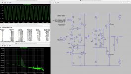
one more of these useless Spice simulations....
this time with laterals and no degeneration in the second and third stage.
Keep in mind that I use the 22R degeneration for the J-Fets only because my Spice J-Fet models have a high Idss around 11mA.
In the circuit I take "naked" J-fets with 7mA Idss.
I ordered some TO-220 lateral Hitachi Mosfets SJ79 and SK216 here
Pacific Semiconductors Inc.- Worldwide Distributor-Import-Export
hope that they are no fakes.
and of course the models for the Hitachi may be not really good.
Attachments
Last edited:
one more of these useless Spice simulations....
this time with laterals and no degeneration in the second and third stage.
Keep in mind that I use the 22R degeneration for the J-Fets only because my Spice J-Fet models have a high Idss around 11mA.
In the circuit I take "naked" J-fets with 7mA Idss.
I ordered some TO-220 lateral Hitachi Mosfets SJ79 and SK216 here
Pacific Semiconductors Inc.- Worldwide Distributor-Import-Export
hope that they are no fakes.
and of course the models for the Hitachi may be not really good.
I have matched jfet models with Idss around 8mA if that helps you out.
If the TO220 devices turn out to be fakes there is no reason not to use the to247 devices. They are very easy to drive.
I have a theory about the "new constant-current bias circuit" .
Fairly sensitive with small changes.
1k/Thermistor was not enough, but 1.6k/Thermistor was too much (ie for what I want). I'm trying 1.24k/Thermistor. Thermistor = NTC 4k7
I'll post results soon.
Obviously values will change again once I add the P Channel part, so this won't be useful to anyone, I'm just sharing observations.
Last edited:
Ok my patience has wore thin. Haha
It will be far quicker to determine this experimentally with thermistor/trimpot combination.
Can't be bothered posting circuit till I have nailed it.
I'll be back.
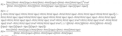
It is hard to adjust more than one parameter at a time, such as the bias current, since it requires at least two temperature points fairly far apart. Unless you are testing with a minimal heatsink, it takes a while to change the temperature. That it why I resorted to solving a system of 3 equations in 3 unknowns, the 3 resistors of the divider TL431 network. Here are the equations for the resistors. Rth1, Rth2, Rth3 are the thermistor resistances corresponding to Vgs1, Vgs2, and Vgs3. You can determine the Rth values for a given temperature using the thermistor R25 and Beta parameters. The equations for R1 ans R3 are not too bad. R2 is a rather huge equation.
Attachments
Yeah I have also done something similar but, I still need to confirm it experimentally and at the moment I'm not sure the thermistor is behaving as hoped by mounting it at the source pin (bolt type thermistor), I might move it to one of the mosfet mounting holes instead.
I need to thermal cycle it again to see what the thermistor is doing.
I'm close though.
I need to thermal cycle it again to see what the thermistor is doing.
I'm close though.
I tried two locations for the thermistor: 1) screwed to the unused source terminal, and 2) Arctic sliver attachment to the center of the SOT-227 package. While making measurements of the thermistor I also took measurements with an ExTech multimeter with a temperature probe attached to the source terminal, and measurements with a digital oven thermometer probe attached to the underside of the heatsink, between fins, directly beneath the SOT-227. The thermistor attached to the source terminal seemed to track best with the other measurements and responded quickest to changes in heatsink temperature.
- Home
- Amplifiers
- Pass Labs
- F4 Beast Builders