Still DEF'in..
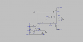
The attached schematic uses a modulated current source [MCS] to drive a basic DEF amp. Please note:
1. OpAmp OPA134PA is a cascoded current source. The collector of 2N3904 cascoding BJT drives the series-connected string of resistors which generate the requisite Vgs for DEF's FETs.
2. The OpAmp is modulated by a music signal [Vin] which is transformer coupled to its non-inverting input. The transformer is a Scosche ground loop isolator.
3. The resultant amp is stable and sounds great.
4. MCS has voltage gain. The driver is the CD player's headphone output
Best
Anton
Attachments
that's thinking outa box
")
Thanks Zen Mod. Attributed to the charm of DEF.
Best
Anton
Still DEF'in..
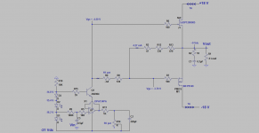
The attached schematic is another version for the previous DEF which was driven by a modulated current source. It is mostly the same circuit as the one I showed in post#341; but to include the following changes:
1. Got rid of the ground loop isolator [GLI]. It has a characteristic sound.
2. I capacitor-coupled the non-inverting input of OPA134PA in lieu of using the GLI. The resistor [10K] in series with the non-inverting input protects it when the [ 0.5uF] capacitor at [Vin] charges up across ~20 Vdc.
3. All of the BJT's [2N3904] collector current [~4.27 mA] flows through the resistor string which [thus] generates the requisite Vgs values for each FET in DEF.
4. The values of the resistors in the parent schematic [post#341] where essentially lowered by the multiplication factor of [0.8227] This factor was derived from the previous 3.52 mA divided by the current 4.27 mA flowing through the resistor string.
5. BTW, the [1 K pot] in the biasing resistor string adjusts idle bias and the [5 K] at the output of the OpAmp adjusts for output offest as taught by Mr. Pass.
6. Amp is stable against oscillation. Its output DC offset hovers within +/- 50 mV. It also sounds great.
Best
Anton
Attachments
maybe a cap across D1 , or completely without xformer (yes , ZM is saying that !) , 47 or something K to D1 , then modulation via cap
Thanks Zen Mod for your recomendations. Will do.
Best
Anton
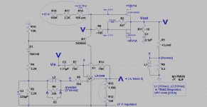
Experimenting with DEF
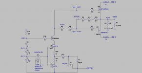
The attached schematic is for a DEF amp which is driven by a modulated current source. Its original schematic is shown in post#344 for possible review. The schematic for this current amp on the bench uses Positive Current Feedback [PCF]. Here is my vision of how it works:
1. The output current of DEF is sensed in the traditional manner as a voltage drop [Vs] across the resistor [0.2 Ohms] which is connected in series with the 4 Ohm load resistor.
2. The resultant PCF voltage [Vs] is transformer-coupled and is also level-shifted to drive the modulated current source which is the OpAmp [LF356N].
3. The two secondaries [rated at 12 Vac/1A each] of the TRIAD Magnetics power transformer are the aforementioned "transformer" which couples [Vs] to LF356N. Clearly overkill for both power and size; but it works quite well to demonstate the concept.
4. Please note the bold character V and its inverted form. They denote the relative phase of the signal being processed. Note the small size of the PCF signal across the 0.2 Ohm sense resistor.
5. LF356N is wired as a buffer. The secondary winding of the transformer is in its feedback loop; meaning it is connected between its output and its inverting input. Note the sum of the two V signals in brackets at this inverting port.
6. LF356N is a special buffer. Its output signal [depicted as an inverted V with a $ sign atop it] is larger in magnitude than that at its non-inverting input. Why?
7. So as to add to the inverted smaller PCF signal and thus generate a signal with a net value and phase which must equal that at the non-inverting input.
8. It follows from the actions in points 6 and 7 [a higher value for inverted V with $ sign atop versus at non-inverting input] that more current flows out of the output of LF356N across its fixed 5 K load.
9. The extra load current of LF356N due to adding [Vs]begins to flow from common, through the DEF load, through the DEF bias resistors, through the emitter of 2N3904, through the joined emitters of the BJTs [comprising the output stage of LF356N and back to ground. This is PCF and its action in this amp
10. The maximun extent of PCF is determined by the 10 Ohm resistor across L1 of the transformer. A value of 12 Ohms [meaning attempting to inject a still higher magnitude of PCF caused oscillation]. So start with a dead short across L1 and add small resistors , and then remove the short to reach the maximum allowed value.
This amp with [PCF] has a characteristic signature in the bass region which was absent from that shown and [listened to] in post #344. It is a high- grade performer.
Best
Anton
Attachments
Last edited:
Experimenting with DEF
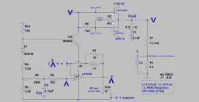
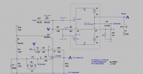
The attached schematic is for a prototype DEF amp. It utilizes a modulated current source driver and also uses positive current feedback [PCF]. Please review the previous post #348 as this one is another variation on its theme. Note the following:
1.The encircled resistors. Their circuits were used to "fine tune" the current flowing through the resistor string which generates the respective Vgs for each FET in DEF. This approach of "bypassing" ~5% of the modulating current source improved idle stability [against drift], and thus enabled a much more stable low level output DC offset.
2. The output current of DEF was sensed in the traditional manner as a voltage drop [Vsense] across a 0.2 Ohm resistor which is connected in series with the output load = 4 Ohms.
3. The primary winding [L1] of the transformers couples the resultant [Vsense] to its secondary winding [L2].
4. The secondary winding [L2] of the transformer is connected in series with the non-inverting input of the modulating current source OpAmp [LF356N]. This connection gave a phase-inverted [V'sense] and shifted its level; meaning referenced it to the [-21Vdc] regulated rail.
5. Please note the bolded V and its inverted forms to help grasp operation of PCF.
6. The audio signal [Vin] is presented to the inverting input of LF356N and is amplified by a factor of 1. The inverted [V'sense] is amplified by a factor of 2 and appears at the output of LF356N in phase for eventual summation with that from inverting amplification.
7. It is clear that the contribution of the amplified [V'sense] at the output of LF356N increases the magnitude of the modulating current source. Consequently, it increases the gain in DEF, and this increased output current [outcome] in the load is thereafter recycled in phase to the non-inverting input of LF356N. This is PCF in this system.
8. An 100 Hz signal was presented at Vin. Its amplitude at Vout was 0.34 Vac and 0.49 Vac with a short [jumper X2] and with the resistor across L2 [330 Ohm] respectively. This calculated to ~3.2 dB worth of PCF [with 330 Ohm ] from the equation 20 log[0.49/0.34].
9. During music listening, the sound of music becomes brigher and less bassy when the shorting jumper across L2 is lifted to expose the system to PCF. Noise as hiss increased also; both of which maybe taken as additional indicators that PCF is engaged/in action.
10. This DEF amp sounds great by using the ADS L730 box speakers. Ditto through two [8 Ohm each], 15" and full-range loudspeakers made by MCM. The two loudspeakers are not enclosed and thus qualify as operating bipolar. Their bass region may benefit due to PCF.
Best
Anton
Attachments
Experimenting with DEF [part 1..its schematic]
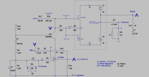
The attached schematic is for another DEF amp prototype. Please review the above post[#349] for background info.
1. It is a current source amp; unlike that shown in post #349 which is a voltage source amp.
2. This amp embodies a modulated current source driver, and uses positive current feedback [PCF] therein. It has the identical count of semiconductors, resistors etc. like that shown in post #349.
The key changes in the circuit of this current source amp follow. Focus on the DEF circuit which is bound by a shaded rectangle.
1. The common sources of the FETs in DEF are grounded. This output stage operates in the common [meaning grounded] source configuration. It inverts the phase of its input signal [at the FETs' gates].
2. The PSU of the DEF amp is the same as that in post #349. Except, the center tap of its power transformer is the power output port.
3. The load is 4.2 Ohms. The resistor [0.2 Ohms] which is in series with the load resistor senses load current flowing through it. Thus, it generates a proportional voltage [Vsense] in a traditional manner for use as PCF.
4. The string of resistors which generates the requisite Vgs to the FETs of DEF starts at the collector of 2N3904 and terminates at [Vsense] .
5. Its all about the proper phase and specific amplitude of the AC signals inside this amp which matter; exactly like that I described in the amp of post #349.
5a. Note the phase dot on L2 which is transmiting [PCF] to the non-inverting input of LF356N.
5b. If you like or choose, reverse the phase of L2 so as to enable instead the status of Negative Current Feedback [NCF]; not tested.
This amp is stable against drift and oscillation. The extent of [PCF] injected therein was measured to be ~ 1.6 dB.
I'll report further on its sonics in the upcoming post.
Best
Anton
Attachments
Experimenting with DEF [Part 2 listening tests..]
The attached schematic shows a slight change from the one I showed in the previous post. By example, the modulated current source starts at the collector of 2N3904, and now terminates at the joined sources of the FETs in DEF which is ground; instead at [Vsense] which is is at the 0.2 Ohm PCF sense resistor. The reason for this change was to squeeze the maximum value/magnitude of PCF this system is capable of
Thus, PCF in this current source amp was measured to be ~3.5 dB at 10KHz, and ~4dB at 100 Hz. It was stable against oscillation.
Like you, I become eager to listen to this amp. So I experiment with different loudspeakers at different locations inside the listening space.
Case1. Listening to a Bipolar Loudspeaker
The two MCM full-range cone loudspeakers are 15 inches in diameter and 8 Ohms each. They were connected in parallel. As a review, they are not enclosed, are bolted to the ceiling rafters, separated by ~10 feet, and they are angled so as to aim at the floor where my head is when I lay on it to listen to their music.
The resultant mono sound of this system is excellent and fully satisfactory. Bass is adequately present and is tight. Please consult US 4,899,387 by inventor Nelson S. Pass; page 3 lines 9 -19. . I am hoping [with extended listening] to connect the performance of the system understudy with that he invented. My hypothessis is that PCF in the current source amp/bipolar loudspeaker combo can and/or does achieve a similar outcome of improved bass performance of his invention.
Case 2. Listening to a Polk Monitor 45 located inside the room.
This commercial loudspeaker [enclosed drivers] was connected to the current source amp via a 2 foot loudspeaker cord; so as to maximize damping of its two woofers. Its bass was soft and weak.. Its resultant characteristic music was not satisfactory. I speculate the cause of this outcome was due to an electrical mismatch between its "internal crossover network" and the current source amp.
Case 3. Listening to a Polk Monitor 45 located in the corner of the room.
I listened to this system as I sat at the opposite corner of the loudspeaker. What a different subjective outcome? The bass erupted, it was deep and articulated. The vocals were clear and so was the rest of the spectrum. The loudspeaker sounded as if it was driven by a voltage instead of a current source amp.
It does pay and be surprised to experiment!
Best
Anton
Attachments
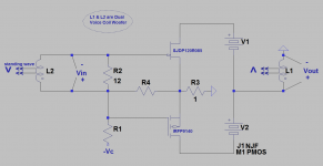
Experimenting with DEF; a Bass Trap
The attached is a schematic of a working DEF amp system which is expected to absorb bass energy in a listening room. Please print the schematic:
1. DEF is configured as a current source amp. This results in a low damping factor [DF] at its power output [Vout]; which is the opposed drains of the FETs. It inverts the phase of its input signal offered to the gates of the FETs.
2. An enclosed dual voice coil woofer [DVCW]. The principal damping of the woofer's cone is believed to be dominated by its "box design".
3. The woofer assembly is a simultaneous moving coil microphone and a bass driver. A good one too. A zero phase delay exists between its two actions and its cone is free to vibrate [acoustic suspension] ; unencumbered by the DF of its driver DEF amp.
4. L2 is depicted as one voice coil of DVCW. It it the microphone coil.
5. L1 is depicted as the second voice coil of DVCW. It is the load of the DEF amp. Note the phase dots on the coils; for proper operation. L1 and L2 are akin to the windings of a transformer.
6. Proper operation is a transformer-coupled positive current feedback [PCF]. The following explains how this bass trap works.
7. A small vacuum [by example] appears in front of the woofer cone because of an [external] negative-going sound wave. It pulls-out the cone. The resultant outward motion generates input signal [Vin] in coil L2 which is loaded with a 12 Ohm resistor.
8. DEF amp amplifies the induced input signal [Vin] and inverts its phase. DEF drives the load coil L1; such that the generated force therein pushes the cone out.. This is the same direction as that from the parent vacuum pulling out the cone. This same direction motion is exclusively a manifest of PCF.
8a.. L1 and L2 are in phase. The simultaneous push-out due to L1 raises pressure at the surface of the cone. Thus it neutralizes or dimishes the initial vacuum due to the cone's pull-out by the negative-going bass wave. The offending bass signal is trapped [wiped-out] and thus is removed from the listening space.
This DEF amp system will oscillate. It is easily stabilized by adjusting the following parameters:
1. Load L2 with a resistor; up to 22 Ohms.
2. Limit the gain of the DEF amp. Its gain is [Vout/Vin] and is the variable impedance of L1 at the operating frequencies divided by 1 Ohm which is at the joint sources of the FETs.
Best
Anton
Attachments
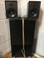
Picture of subwoofer under study placed in room corner
The attached picture pertains to the previous post and upcoming ones of this study. It shows a dual voice coil subwoofer; [containing an internal Xover] and its satellites. This picture and details have already appeared in the thread "DIY the device of US 4,899,387"; post#88.
Best
Anton
The attached picture pertains to the previous post and upcoming ones of this study. It shows a dual voice coil subwoofer; [containing an internal Xover] and its satellites. This picture and details have already appeared in the thread "DIY the device of US 4,899,387"; post#88.
Best
Anton
Attachments
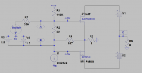
The schematic in post #352 may not have made sense. The input signal [Vin] is shown as differential rather than common when presented to the gates of the FETs. The attached schematic for the amp understudy unravels the consequences of this unusual approach as discussed below:
1. The core schematic is a simplified version of the " current modulated" one which I posted earlier. It is essentially, the components to the right side of the encircled letters A and B.
2. Two independent AAA batteries are shown to the left side of the encircled letters A and B. Either one is selected by a switch. The resultant current which circulates in the closed loop generates a voltage drop across the 22 Ohm resistor per Ohm's Law. This voltage drop is the aforementioned differential signal [Vin].
3. At the neutral position of the battery selection switch [N/C], there is an idle [~ 0.2 mA] which flows across the 22 Ohm resistor and generates a [Vin = ~4.5 mV]. The amp is stable and is adjusted [with offset control] to have a ~0 Vdc output offset [letter C].
4. When the switch selects positive battery [V3], I measured a [Vin =~85 mV ] across the 22 Ohm resistor. Point A is more positive than point B. It follows that when point A went positive [relative to common], point C at the output went negative [relative to common]. Thus points A and C are out of phase. Or points B and C are taken to be in phase; because when point B went negative [relative to common] so did point C.
5. When the switch selects the negative battery [V4], I measured a [Vin = ~75 mV] across the 22 Ohm resistor. When point A went negative point C went positive; both relative to common. Thus and again, points A and C are out of phase.. When point B went positive so did point C at the output. Thus and again, points B and C are in phase
The earlier schematic in post #352 showed two coils L1 and L2 which belong to a Dual Voice Coil subwoofer. Please note the phase dot on coil [L2] which is at the same equivalent point B of this schematic. And the phase dot on coil [L1] which is at the power output at the equivalent point C of this schematic. This specific connectivity of the coils [L1 at point C and L2 in phase at point B] is to account for generating therein this amp the described positive feedback [PF or PCF] and its potential use to suppress standing waves.
Best
Anton
Attachments
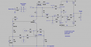
A versatile DEF amp..its schematic [part1]
The core of its schematic is like the one I posted earlier and named a "current modulated DEF amp". It shows:
1. R11 [330 Ohm] and C1 [220 uF] at its power output bias the FETs, and further enable a simple approach to a robust DC Servo. This [inverting] servo locks the output DC offset at <10 mV. I've used this approach before.
2. I also used in this DEF amp the two voice coils [L1 and L2] of the dual voice coil [DVC] subwoofer [see recent picture of it placed in corner] using the scheme of positive feedback [PF] and/or positive current feedback [PCF] which I had already discussed in my last posts.
3. I had given this positive feedback scheme the earlier name of a bass trap. I rather call this approach the more appropriate Music Clarifier. It does and/or is supposed to exactly do this.
4. This versatile DEF amp has the option of five music signal inputs. They are the encircled locations A, B, C, D, and E. Please note the Input Select Switch at top left part of the schematic. Each input connection gave a different sound outcome.
5. I'll post the scheme which I used to listen to this audio system so as to assess its musical value.
Best
Anton
Attachments
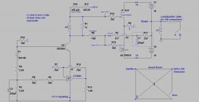
DEF Amp used as Clarifier
The attached schematic is the same one I showed in the previous post. However, it does not use an input music signal. Instead, it is used as a Clarifier. This "music clarifying" performance is due to the attenuation of standng waves [SWs]. [SWs] are late echoes which bounce back and forth in the confines of the sound room. Please note the following simple testing scheme:
1. The bottom right of the view depicts the sound room. The right corner has the sound generator which is an ADS L730 loudspeaker. It is driven by one channel of a THRESHOLD S/150 power amp The input signal to this power amp is an adjustable sine from a function generator. It can also be a music signal from the headphone output of a SONY CD player.
2. The sound room shows the placement of the Clarifier. It is the DEF amp plus the loudspeaker system in the corner [pic in post # 353].
3. {I} can sit at the intersection of the floor diagonals or at the corner facing ADS L730.
4. Per the PASS patent US, 4,899,387; page 1 lines 40-43, the most offending [SW] is the one which has the wavelength of the longest diagonal in the sound room. It is ~30 feet which is that for ~37 Hz. This wavelength corresponds to the diagonal from the ceiling corner to any opposing floor corner.
5. Note the encircled loudspeaker [2-conductor] cable at [Vout]. It is ~12 feet long and is used to do an A/B comparison; meaning to [remotely] and manually short Vout or Not.
6. DEF in this application is a current source amp. Its power output [Vout] can be shorted to ground without damage. Shorting [Vout] to ground disables the Clarifier [position B] versus enabling its action at position [A]. This A/B comparison is under my control.
7. I filled the room with a ~37 Hz. sound signal. I used an analog sound pressure meter.
7a. With the meter ~3 inches in front of the Clarifier's DVC woofer, I measured 70 dB at position B [Clarifier disabled/output shorted.]. I then saw the meter's needle drop by ~ 4 dB at position A; meaning when the Clarifier was enabled or the output was not shorted to common.
7b. The Clarifier lives up to its reputation/performance; by diminishing the sound intensity of the 37 Hz. echo.
Best
Anton
Attachments
Can this jfet work?
UJ3N120070K3S UnitedSiC | Mouser
"Normally on" mean it's depletion mode? A voltage is needed to stop it from conducting?
UJ3N120070K3S UnitedSiC | Mouser
"Normally on" mean it's depletion mode? A voltage is needed to stop it from conducting?
Ugs for 2A is in range of -10V
And this makes it difficult to match to a P-ch enhancement mode mosfet...
I'm asking because I don't want to use up my R085 jfets.
Was going to buy something to experiment with.
Any modern, available power jfets recommended?
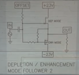
There's also this schematic with the two resistors or variable resistors.
What values will work?
thx.
Attachments
Last edited:
- Home
- Amplifiers
- Pass Labs
- DEF Amp