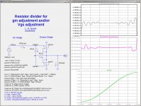
Here is a circuit that should allow one to adjust for Vgs mismatches between the SIT and the PFET without using source resistors. It does not attempt to change the transconductances of either FET.
It is good to know that what I only thought as the possibility is a viable solution, in a refined method.
")
Have you tried this? In reality what could be the steps to set the bias/voltages?
Last edited:
My experiments have been simulations only. I have not built any of the DEF Amp or DEFiSIT circuits because I do not have any depletion mode NFETs or SITs.It is good to know that what I only thought as the possibility is a viable solution, in a refined method.
Have you tried this? In reality what could be the steps to set the bias/voltages?
It is good to know that what I only thought as the possibility is a viable solution, in a refined method.
Have you tried this? In reality what could be the steps to set the bias/voltages?
Hello Chul. May consider using the general solution by Mr. Pass to tackle your request above. I have used it successfully. It is shown in the schematics of posts #98 and #107. Please note:
1. The resistor which bridges the gates of the FETs adjusts bias; meaning the idle current of the FETs. It is best to use a variable resistor [pot]. The higher its relative value is, the lower the bias; because it makes Vgs of the depletion FET more negative by pinching off [closing] its Vds channel.
2. The variable resistor connected to the most negative rail adjusts output offset.
Best
Anton
The equations for the gm of the NFET and the input impedance to the resulting output stage are given in post #1587 of the F4-Beast-Builders thread F4 Beast Builders.
Hello Chul. May consider using the general solution by Mr. Pass to tackle your request above. I have used it successfully. It is shown in the schematics of posts #98 and #107. Please note:
1. The resistor which bridges the gates of the FETs adjusts bias; meaning the idle current of the FETs. It is best to use a variable resistor [pot]. The higher its relative value is, the lower the bias; because it makes Vgs of the depletion FET more negative by pinching off [closing] its Vds channel.
2. The variable resistor connected to the most negative rail adjusts output offset.
Best
Anton
Hi Anton,
I saw the circuit on #98 and it is interesting. It has some similarity to the 'filament bias' circuit of tube amp, that use conctant current circuit for heater but then go through small value resistor and forms the bias voltage for the direct heated tube. The current for the heater is rather high thus small value resistor can be used for certain bias voltage. This eliminates the bypass capacitor. Just like the 100ohm resistor in your circuit.
I think there can be other approach like applying a variable current souce circuit to the 100 ohm resitor only, and varying the current limit to adjust the voltage drop across the 100 ohm which is the difference of the Vgs between SIT and FET?
Last edited:
My experiments have been simulations only. I have not built any of the DEF Amp or DEFiSIT circuits because I do not have any depletion mode NFETs or SITs.
Hi Lynn,
I think the circuit is still feasible, though i am not so knowledged to determine.

Hi chul, The resistance network illustrated by Mr Pass is a simple and elegant solution.
I hope this helps.
View attachment 695522
Thank you Claudio,
Now I see how the calculation.
May I ask more questions?Vdc at output is 0 not to use the capacitor. But you need to adjust the Iq to some value, say 1.5A, which is subject to other conditions like Vds. So these affect each other..? Are the -3.76 and -3.65 are fixed values that are determined before?
What if I just use output capacitor? Does this make it easier?
Thank you in advance.
Of course you can always use a conventional bias circuit, just make sure
the bias polarity is in the direction you want.

Thank you for confirming that. I wonder what would the difference in sound with/without the 0.6ohm Source resistor in my 2SK82/IRFP9240 circuit. Maybe my ears can tell.. or can't.
In my country, we are having a record hot weather these days. This morning I checked the AC power voltage and it was 201 VAC(! air conditioning ?), not the nominal 220VAC. So if I use some regulated Vds adjustment to unregulated bridge-capacitor supply, would this affect the bias in worse direction?
Hi Chul, Vds and Id are initial project data. I chose +/-24V and 1.3A. With the two data have to measure the two Vgs. The test circuit is in posts #90 and #93. You have to wait at least 30 minutes for everything to stabilize. The two Vgs must be as close as possible. Before building the DEF, try to simulate it. It's not important which NJF you will use. This will allow you to understand that to reach 0Vout a precise resistors value is necessary. As shown by Antoinel it will be necessary to add a small trimmer to R3.
Imput impedance will be low. This will also be evident in the simulation. To increase it you can use the bootstrap capacitor and increase the -Vdc of the resistors.
Imput impedance will be low. This will also be evident in the simulation. To increase it you can use the bootstrap capacitor and increase the -Vdc of the resistors.
Here is a way to see the gm of the output stage and the input impedance. Look carefully at the expressions in the top two plots, the .measure commands in the .asc file, and the resulting log file output.
Thank you, very very interesting
Thank you for confirming that. I wonder what would the difference in sound with/without the 0.6ohm Source resistor in my 2SK82/IRFP9240 circuit. Maybe my ears can tell.. or can't.
In my country, we are having a record hot weather these days. This morning I checked the AC power voltage and it was 201 VAC(! air conditioning ?), not the nominal 220VAC. So if I use some regulated Vds adjustment to unregulated bridge-capacitor supply, would this affect the bias in worse direction?
0.6 ohm Source resistor will make a difference, particularly if you tap
the speaker output at one Source pin vs the other. Off the SIT, you
typically see less 2nd harmonic, Off the P ch, more.
I personally find the undegenerated output more interesting sonically.
As to the power, regulated DC reference is best, as it leaves constant
DC value for Vds for the SIT, which is more sensitive than the P ch
Mosfet.
Indeed the undegenerated one sound better to me!
I took out the 0.6 ohm resistor and across the 100ohm resistor tested a CCS circuit of 10mA (simple DN2540 - 500ohm pot to adjust - 12V battery, not referenced to ground) this worked just OK and now I can adjust current, Vgs, and also the voltage across the SIT. I will add a simple 15V supply for the CCS and this way I can play with more SITs that are just sleeping in the box.. Thank you.
@ Claudio
Thank you for the explanation and now I see better. I am a kind of chicken to try without output capacitor. But in time I may be confident...
I uploaded what I did here;
http://www.diyaudio.com/forums/pass-labs/314822-greedy-boy-defisit-papas-koans-62.html#post5510232
http://www.diyaudio.com/forums/pass-labs/314822-greedy-boy-defisit-papas-koans-62.html#post5510232
New DEF Schematic
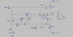
The attached is a new DEF schematic. Some details are:
1. I used a fixed +/- 16 Vdc PSU. Idle drain current for each FET in DEF was 1 Amp.
2. DEF can use Vin[A] or Vin or [Vin A] plus Vin simultaneously. The line amp sourcing the two identical Vin[A/B] is a CD player's headphone output. It has plenty power drive.
3. The hypotheses therein circuit are that the BJTs do error correction, bootstrap and possibly introduce positive current feedback [PCF] inside DEF. If this hype is valid, the added complexity beyond that of the basic DEF by Mr. Pass [meaning no BJTs] maybe accepted as valuable.
4. This DEF embodies several operational variables. For example by using Vin[A] or Vin or Vin[A+B] to name a few. May have a positive and/or perceptible effect on performance.
5. DEF sounded great [as an example] with the input signal simultaneously injected at the gates of both FETs [why not for a change?]; meaning {Vin [A+B]}. And the output capacitor [220uF] was also engaged at position 1 of the switch. This cap is believed to alter the gain of the BJT complex.
6. The shown BJTs are both Germanium. Delta Vgs of the FETs was ~0.75V. It is also called the [Vcb] for 2SB186. I felt this Vcb may be too low to allow for the proper operation of a typical Silicon BJT; like 2N3906.
Best
Anton
Attachments
- Home
- Amplifiers
- Pass Labs
- DEF Amp