

I built up my power-on-set and power-on-clear logic into SPICE, and it did what I thought it should do.
So I built it up on the breadboard (again), and it worked there too.
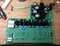
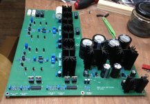
But on the real PCB the CLR line was being held high, and one of the flip-flops was getting hot. 3 of the flip-flops are wired identically, so the odds pointed to trouble with the one that was getting hot rather than a design or layout error.
Of course the flip-flop is in a 14-pin package whereas the IRF610 it's driving is in a 3, so the 610 came out first. No joy.
Next out came the flip-flop. (And the capacitor next to it after a close encounter with the soldering iron.) The CLR line now came down nicely after startup, and the other flip-flops started working correctly. In went a new flip-flop, IRF610 and capacitor, and everything is ducky.
It's pretty humid in Ireland and I'm pretty careful about grounding myself, so I doubt it was static. Might I have overheated it when soldering? (The part in question is a CMOS CD4013.)
Cheers,
Jeff.
So I built it up on the breadboard (again), and it worked there too.
But on the real PCB the CLR line was being held high, and one of the flip-flops was getting hot. 3 of the flip-flops are wired identically, so the odds pointed to trouble with the one that was getting hot rather than a design or layout error.
Of course the flip-flop is in a 14-pin package whereas the IRF610 it's driving is in a 3, so the 610 came out first. No joy.
Next out came the flip-flop. (And the capacitor next to it after a close encounter with the soldering iron.) The CLR line now came down nicely after startup, and the other flip-flops started working correctly. In went a new flip-flop, IRF610 and capacitor, and everything is ducky.
It's pretty humid in Ireland and I'm pretty careful about grounding myself, so I doubt it was static. Might I have overheated it when soldering? (The part in question is a CMOS CD4013.)
Cheers,
Jeff.
CD4000 series logic is reasonably well engineered for ESD hardness so I suspect either (a) you had bad luck and got a dead part right out of the tube; or else (b) your circuit has a connection error which destroyed the chip. If you install a DIP socket you can cycle through three or four brand new, fresh, virgin chips. This will tell you whether that one original part was dead, or whether your PCB itself is the culprit.
Yep, looks like a tap on the shoulder from protector of Pass Lab.... it's looking more like a duff part...

Last edited:
be happy
just small Audio Gods are against this thread
And me too. It breaks the habits here.
Thanks for the info, Mark.
While I didn't install a socket, the second CD4013 I installed is working fine through several power-cycles. So there could still be some edge condition, but it's looking more like a duff part.
Cheers,
Jeff.
Check D1/D2 (D5/D6), but properly... get them off the PCB.
Last edited:
I think I might have used a colloquialism with insufficient ubiquity. When I said "everything is ducky" that meant "it works great!". So all the issues were fixed by replacing the CD4013.
However, I'm not following the second part of this:
Do you mean: elevate the diodes from the PCB because they're going to get hot, or...
the diodes shouldn't be in the design at all (but then pressing a button will latch both flip-flops, no?), or...
the CD4013 should be off the PCB (ie: in a socket)?
Cheers,
Jeff.
However, I'm not following the second part of this:
Check D1/D2 (D5/D6), but properly... get them off the PCB.
Do you mean: elevate the diodes from the PCB because they're going to get hot, or...
the diodes shouldn't be in the design at all (but then pressing a button will latch both flip-flops, no?), or...
the CD4013 should be off the PCB (ie: in a socket)?
Cheers,
Jeff.
You mentioned that "everything is working fine through several power-cycles. So there could still be some edge condition". In my experience, those little glass passivated didoes could go faulty, but only just, the consequence of which would manifest in the way you described the problem. To detect a dogy diode, it was necessary to lift one end off the PCB, hence my suggestion.
But if it's all good then Bob's your uncle.
But if it's all good then Bob's your uncle.
- Home
- Amplifiers
- Pass Labs
- Pass HPA-1, what do we know?