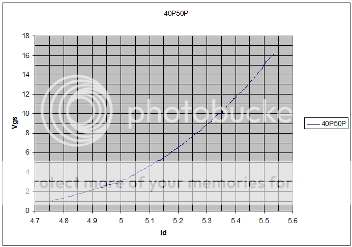
Show me Id vs Vgs and gm vs Id with Id in the range of 0A to 3A. The datasheets are useless in that range, and extrapolating the curves down into that region will not be accurate. Actual device measurements are needed at the operating conditions of the device.
Yeah fair enough. They follow the data sheets fairly closely, but if the data sheets are wrong we're back to square one.
Either way my parts are on the way and it will be fun building it.
It should be fairly straight forward.
I used Lynns draft, with less voltage and no cascoding and no cascode feedback.
http://www.diyaudio.com/forums/pass-labs/295387-villars-2007-power-amplifier.html#post4799626
of course less voltage +/-23V and biased at 1.3A following Nelson BAF talk.
But if I were you I would wait building!
Look some time at the Villars.
Biasing is very similar to F4, frontend is very similar to Sony II.
I am sure Lynn and 2picodumps will do better drafts.
Better bias stabilization and possible pos feedback.
Maybe we should take away this build inspired by the XA25 in a different thread.
The decisive is the use of the IXys and not so much Nelsons for sure more clever implementations we do not know.
I used Lynns draft, with less voltage and no cascoding and no cascode feedback.
My SPICEd version is similar, except I used global feedback from output to the JFET sources.
How did you implement the thermistor to control the bias drift? Are you using TL431? I have a simple idea of how use a thermistor with the TL431, but am unsure what value I would need to accomplish my goal.
Last edited:
I am sure Lynn and 2picodumps will do better drafts.
Better bias stabilization and possible pos feedback.
.
Maybe a little different but I don't think it will be better. I generally keep to the KISS to do the job, For example mine will probably have no thermal compensation, hahahaha.
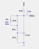
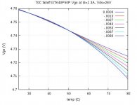
After understanding that capabilities of the IXYS hocky-pucks better, I conclude that there is absolutely no need for Positive Current Feedback (PCF). Wrt. the bias circuit: I did some serious equation analysis a simple thermistor based TL431 bias circuit. By measuring the bias voltage needed for the desired idle current at 3 temperatures, such as 25C, 50C, and somewhat higher, one can solve a system of equations for 3 resistors in the bias circuit so that the ible current will be nearly constant between 25C and 50C. Shown are the circuit, and some Vbias .vs Temperature curves showing the output from the bias circuit as the temperature to the thermistor (NTC) changes.
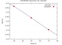
- The first plot shows big red dots where the circuit Vbias was measured for 1.3A bias idle current, and the behavior of the bias circuit that was fit to the measured data.
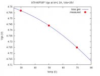
- In the second plot I intentionally lowered the Vgs value of the 70C measurement so that the bias generator would exhibit a fairly constant current behavior between 25C and 50C, but gradually reduce the bias current at temperatures above 50C.
- The third plot shows a family of possible bias curves for different amounts of Vgs reduction at 70C.
Attachments
My SPICEd version is similar, except I used global feedback from output to the JFET sources.
How did you implement the thermistor to control the bias drift? Are you using TL431? I have a simple idea of how use a thermistor with the TL431, but am unsure what value I would need to accomplish my goal.
I will answer tomorrow...
")
Maybe we should take away this build inspired by the XA25 in a different thread.
The decisive is the use of the IXys and not so much Nelsons for sure more clever implementations we do not know.
Maybe we should call it "F4 Monster (add whatever front end you like)"
After understanding that capabilities of the IXYS hocky-pucks better, I conclude that there is absolutely no need for Positive Current Feedback (PCF).
I thought this was immediately obvious.
After understanding that capabilities of the IXYS hocky-pucks better, I conclude that there is absolutely no need for Positive Current Feedback (PCF). Wrt. the bias circuit: I did some serious equation analysis a simple thermistor based TL431 bias circuit.
[/LIST]
I can confirm that with a TL and an thermistor on the heatsink the bias is very stable.
I did not yet measure the damping, so you think that the very high values Nelson claims for the XA25 are possibly a result of the pucks traits?
Initially I did not think the IXSYS parts would get you to a damping factor of 700 without either lots of negative feedback, or PCF. I now know better.I thought this was immediately obvious.
Initially I did not think the IXSYS parts would get you to a damping factor of 700 without either lots of negative feedback, or PCF. I now know better.
Yeah, just one of those brain fart moments. I have them all the time.
I started a new thread
the promised combination of circuits running at my home is here.....
Thanks for hosting 2picodumbs
http://www.diyaudio.com/forums/pass-labs/300233-f4-beast-builders.html#post4907883
Thanks for hosting 2picodumbs
http://www.diyaudio.com/forums/pass-labs/300233-f4-beast-builders.html#post4907883
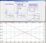
In post #130 Pass XA25? I discussed bias circuits for the output fets. There is an LTSpice simulation comparing 3 bias circuits for an IXTN40P50P operating between 25C and 75C with 24V rail voltages, and 1.3A (approx) bias current.
The Thermistor Controlled Constant Current circuit tracks very well with the "ideal" Constant Current Servo.
- Constant Voltage Bias
- Thermistor Controlled Constant Current Bias
- Opamp Servo Constant Current Bias
The Thermistor Controlled Constant Current circuit tracks very well with the "ideal" Constant Current Servo.
Attachments
- Home
- Amplifiers
- Pass Labs
- Pass XA25?