Not surprising, they were in the original flats taken in sequence, so there was
a good chance of getting the same die, and they were all tested on a
temperature regulated 50 deg heat sink and then sorted by Vgs.
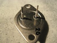
Looking at large numbers of them, there is great consistency. Of the 2000
or so I tested, I had one bad one.
Thanks again!
2000 VFETs
 respect!
I'm always wondering how long it took to measure them all, a few days, weeks, months? say 5 minutes per VFET = 10.000 minutes /60 = 166 hours. That's four full 40 hours workweeks.

Yep, finished the second big output stage this weekend....lots of work done, lots of work still to do
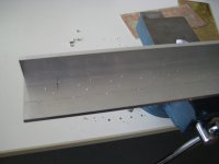
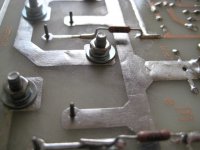
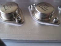
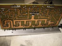
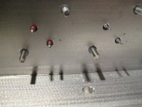
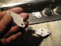
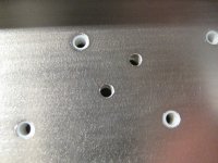
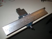
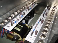
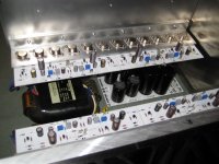
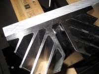
I attached some photos, of the mounting of the VFET's. The M3 bolds are isolated with teflon tube, just like the other gate and source pins. I kept the holes as small as possible so there is a lot of contact surface between the aluminum and the VFET.
This output stage is with the superb matched VFET's from DIYAudio store and measuring the output stage showed a perfect current distribution between the VFET pairs.
The mica and goop took a while, and can be cleaned with tissues and isopropanol fairly easy.
Attachments
-
 IMG_6077ww.jpg209 KB · Views: 907
 -
 IMG_6126ww.jpg397.5 KB · Views: 400
 -
 IMG_6120ww.jpg399.9 KB · Views: 461
 -
 IMG_6119ww.jpg388.8 KB · Views: 455
 -
 IMG_6117ww.jpg356.8 KB · Views: 374
 -
 IMG_6114ww.jpg464 KB · Views: 341
 -
 IMG_6110ww.jpg223.8 KB · Views: 852
 -
 IMG_6106ww.jpg410.5 KB · Views: 861
 -
 IMG_6105ww.jpg534 KB · Views: 873
 -
 IMG_6083ww.jpg242.5 KB · Views: 891
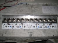
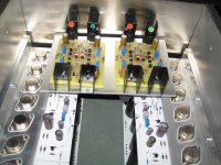
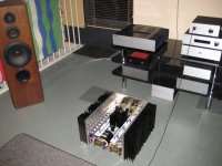
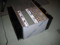
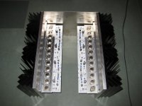
And some more pics of how I think to lay-out the amp.
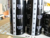
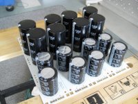
Capacitors are in, bought some 105 Celsius types, total of 216.000 uF per channel almost half a Farad for the whole amp
The heatsinks are attached with 3 M5 bolts each, should I use spring washers also? because of the change of temperature all the time?
The heatsinks inside the enclosure are for the rectifier diodes.
The amp is really big
Capacitors are in, bought some 105 Celsius types, total of 216.000 uF per channel
almost half a Farad for the whole amp The heatsinks are attached with 3 M5 bolts each, should I use spring washers also? because of the change of temperature all the time?
The heatsinks inside the enclosure are for the rectifier diodes.
The amp is really big
Attachments
-
 IMG_6151ww.jpg384.4 KB · Views: 554
 -
 IMG_6162ww.jpg358.7 KB · Views: 535
 -
 IMG_6149ww.jpg355.7 KB · Views: 493
 -
 IMG_6148ww.jpg329.3 KB · Views: 446
 -
 IMG_6146ww.jpg310.1 KB · Views: 456
 -
 IMG_6141ww.jpg321.2 KB · Views: 431
 -
 IMG_6139ww.jpg386.4 KB · Views: 382
 -
 IMG_6099ww.jpg427.6 KB · Views: 418
 -
 IMG_6097ww.jpg362.5 KB · Views: 456
 -
 IMG_6164ww.jpg411.6 KB · Views: 537
that's going to end up being a 20w/ch amp, no?
wow.. wonderful build.
It's balanced so probably closer to 80W/ch.
Can't wait to see it done.
Thanks everyone, I have 2 x 24V transformers, hopefully they give about 34V after rectifying, and as in the original article there will be 10 volts over the cascoding IRF's MOSFETS. So there will be 24V on the VFET's. Say a clear swing of + and - 20 Volts x2 balanced is around 40 Volts. So around 100Watt in 8 Ohms I guess.
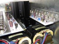
I'm testing the second channel now with around 220 Watt dissipation everything seems to work out fine. I'm so glad I used a 15mm thick aluminum heat spreader. It evenly heats up the heatsinks.
Would it be worth the money to use expensive thermal compound like 'Arctic Silver 5' with those big 450 x260 mm areas? Or would the normal cheap white silicone 'Goop' be good enough.
What do they use at Pass Labs ?
Would it be worth the money to use expensive thermal compound like 'Arctic Silver 5' with those big 450 x260 mm areas? Or would the normal cheap white silicone 'Goop' be good enough.
What do they use at Pass Labs ?
Arctic silver has terrible flow properties, you don't want that for such a large area.
At Pass labs I suspect they rely on proper machining of the surfaces and use nothing.
be it Wayne or Pa , I believe they will confirm use of proper white goop
much less expensive than NASA level of machining
that would be common ZM logic
When you put it like that. I certainly agree.
But you can certainly start going backwards with goop ie get worse performance using it than not using it. The trick is you want just enough to do the job and no more, that can possibly present it's own challenge when used over a very large surface area.
I don't know where this optimum point is but maybe it's not at the NASA level surface finish.
I think if I was doing it, I'd get the goop then thin it out with the appropriate solvent so it's at the viscosity of paint or lower and apply it with a brush then let the solvent evaporate off then bolt the heatsink, and heat spreader together. Then hopefully Bob's you uncle.
This is a good reason why I avoid that type of heatsink set up, I don't want to put at risk losing any more of my 2.5 brain cells.
Last edited:
Hi Walter,
not quite your size but i also used white goop under my 15mm heatspreaders
(the heatsinks base is soo thin) evenly spread with my thumb on both surfaces
and firmly bolted together 'till the juice comes out.
go for it!
A.
http://files.diyaudio.com/forums/gallery/data/1527/medium/IMG_5717.JPG
not quite your size but i also used white goop under my 15mm heatspreaders
(the heatsinks base is soo thin) evenly spread with my thumb on both surfaces
and firmly bolted together 'till the juice comes out.
go for it!
A.
http://files.diyaudio.com/forums/gallery/data/1527/medium/IMG_5717.JPG
Last edited:
What do they use at Pass Labs ?
Heat sink metal on metal? Smooth extrusions and lots of big bolts.
- Home
- Amplifiers
- Pass Labs
- VFET-X (or my 1/3 40th Anniversary Sony VFET Clone)